Author Archives: Sudar

About Sudar

I am WordPress plugin developer and the original developer of Bulk Delete and Bulk Move WordPress plugins.

Got my hands on the Pi ;)

raspberry pi up and running

Finally, after waiting for more than six months I got my on hands on a Raspberry Pi (in fact 4 of them πŸ˜‰ )

Ever since I heard about Raspberry Pi, I wanted to try one, especially to compare it with an Arduino and finally the day has arrived πŸ™‚

Buying Raspberry Pi in India

It was slightly difficult to buy a Raspberry Pi in India. It was either out of stock in most online retailer sites or was prohibitively expensive. There were even sites that were selling it for Rs. 4500 (~ $85). The Indian version of element14 was selling it at Rs. 2750 (which is slightly high, but still okay when you consider tax etc) but model B of Raspberry Pi was out of stock for pretty much most of the time.

Update: It is now available in SP road (Bangalore) for around Rs. 3200.

How I bought Raspberry Pi?

raspberry pi up and running
Luckily for me, a colleague was traveling to US on a business trip. I bought it from element14/Newark and shipped it to my friend who picked it up for me on the way back to India. So far this seems to be easiest and the cheaper option to buy Raspberry Pi in India.

And by the way, they have also given me a Voucher code NEW2P which will give you 15% off components that you buy from element14/Newark. Feel free to use it. I think the offer ends by 31st Jan.

First impression

Even though I have seen one in photos, it was still existing to hold one up in your hand and realize that it has more processing power and memory than the desktop I bought for about a lakh (~ $2000) just 10 years before πŸ™‚

Starting it up

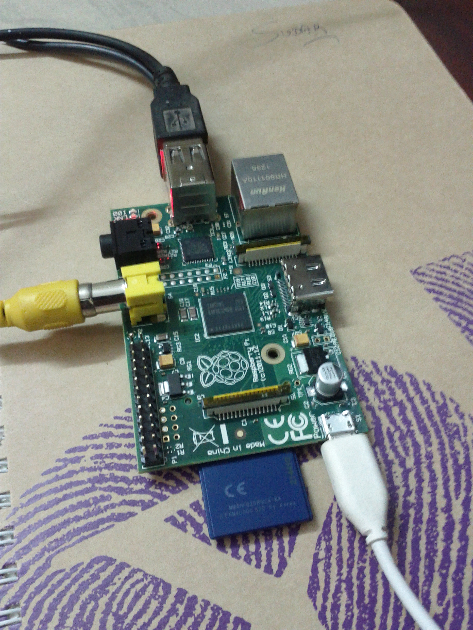
I didn’t have a proper power adapter for powering up Raspberry Pi. So I took an iPad adapter and a kindle cable to power Raspberry Pi.

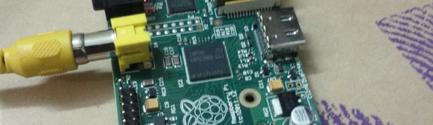
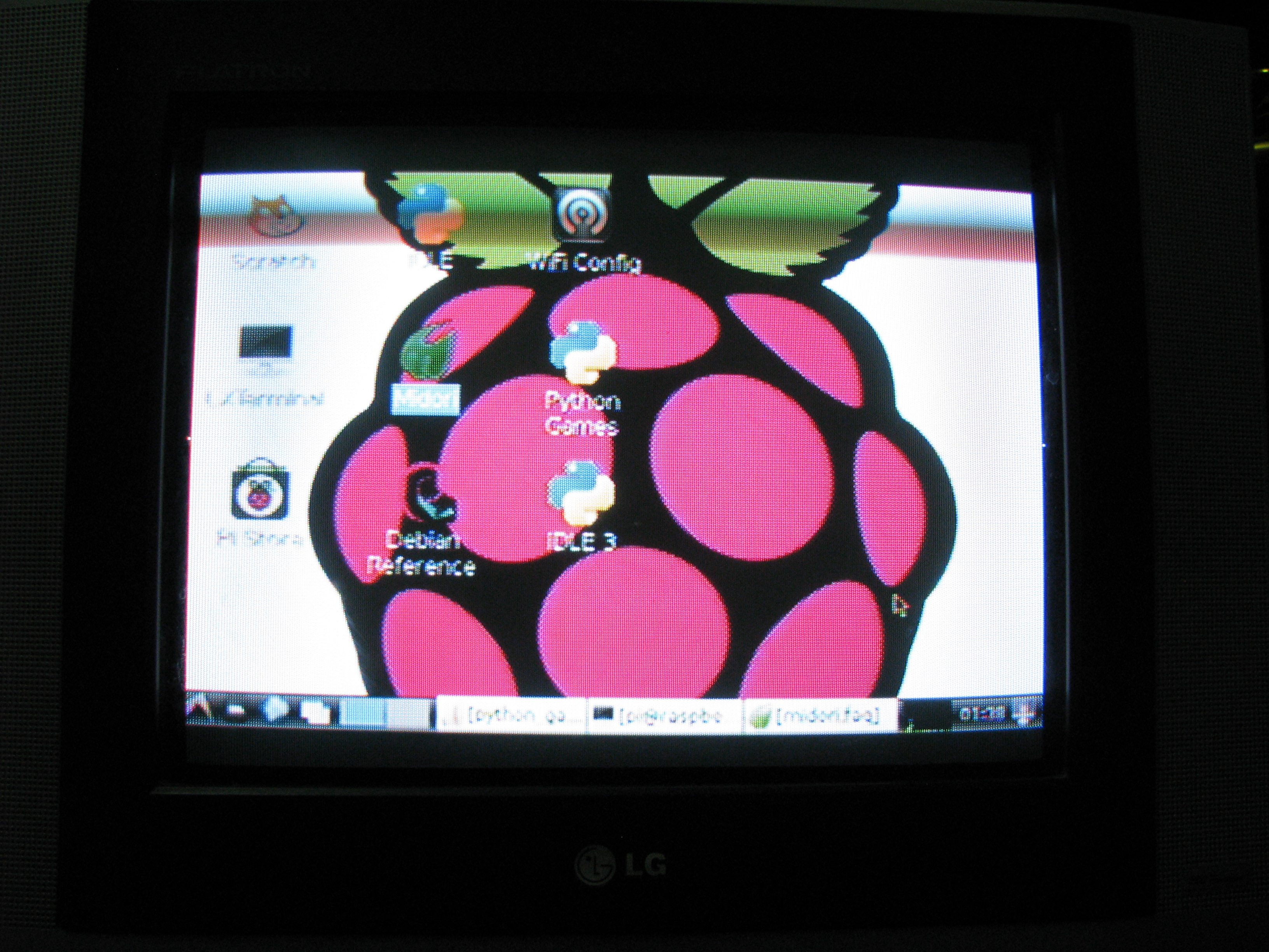
I then realized that I don’t have a monitor which will work with Raspberry Pi. My old monitor was just plain VGA and the slightly new one supported only DVI-B. Luckily Raspberry Pi has the composite video option and I was able to connect it to my TV. Even though the resolution wasn’t great, I still was able to boot the default OS image that I downloaded from Raspberry Pi’s website. Below are some pictures of it running in my TV.

raspberry pi running in my TV
I will soon write another article about the accessories that you have to buy in addition to Raspberry Pi, to get the most out of it.

What’s next?

I am really excited now and my mind is already bubbling up with lot of ideas. The first idea is to connect it to an Arduino and try to control my Arduino based Asimi bot. When you connect a Raspberry Pi to an Arduino, the possibilities are endless πŸ™‚

Since I am having 4, I am planning to use one as a dedicated media center. I am thinking of loading XBMC on one of the Pi’s and permanently connect it to my TV.

Stay tuned for more updates and projects as I continue to play around with it πŸ™‚

Arduino Robotics workshop – second batch

The dates for my second batch of Arduino Robotics workshop is confirmed now. It is going to be on Jan 26th and 27th.

It is going to be a 2 full day workshop, like last time and I will also be providing the components needed for the workshop. You can find the course content, fees structure and the registration process in the workshop page.

The aim of the workshop is that at the end of two days you should able to have a working Arduino based bot which can autonomously run on its own avoiding obstacles in the path.

Photos from my earlier workshop

Also checkout some of the photos from the previous workshop

arduino-robotics-workshop-5 arduino-robotics-workshop-3 arduino-robotics-workshop-2 arduino-robotics-workshop-1

[mailchimpsf_form]

Using Arduino as a bridge to connect serial devices with PC

I recently found an interesting use of the many Arduino boards that I have. You can use your Arduino board as a bridge to connect serial devices to the computer, without even writing a sketch. How cool is that? πŸ˜‰

Before I tell you how you can do it, let me explain about virtual COM ports and how Arduino uses them.

Virtual COM ports

The ATmega328 microcontroller used in the Arduino board supports UART TTL (5V) serial communication. You can connect the microcontroller to the serial port in your computer (with appropriate logic level converters) and can interface with it.

But these days, most computers don’t have a serial port. So the Arduino team when they designed the board, placed another IC to channel this serial communication over USB. In pre-UNO boards this is handled by the FTDI FT232RL IC and in UNO it is handled by ATmega8U2 IC. In your computer, you will have to install corresponding drivers and the device will appear as the virtual COM port.

Holding the processor in RESET mode

The serial to USB(TTL) IC (either FTDI FT232RL or ATmega8U2) is connected to Arduino pins 0 and 1. If we hold the processor in RESET mode, then all its GPIO pins will me in tri-state, effectively removing it from the circuit and you can directly interface the serial to USB IC with your device.

To hold the processor in RESET mode, just connect the RESET pin (which is active-low) with the ground. This will hold the processor in RESET mode.

Interfacing the serial device

Now you can connect the serial device to the Arduino pins 0 and 1. You should however note that the Rx pin (pin 0) goes to the Rx of the device and Tx pin (pin 1) goes to the Tx of the device and not the other way around.

In your computer the device will appear as a Virtual COM port. You can connect to it using programs like screen or hyper terminal.

I didn’t had a serial device handy with me, so I used a another Arduino as a serial device to test this. I wrote a small sketch which was printing something in the Serial every few seconds and then when I opened the virtual COM port using screen, I was able to see its output.

This is a neat trick and might be useful if you have to interface some serial device like a GPS or a Bluetooth module with your computer.

Happy hacking πŸ™‚

Testing TI Stellaris LM4F120 LaunchPad using demo program

TI Stellaris Launchpad

TI’s Stellaris LaunchPad board, which I reviewed recently comes with an out of the box demo program called qs-rgb. This program allows you to test the LaunchPad board and also try out some of the features of the LM4F120 MCU that is present in the board.

Getting the program into the board

When you buy the board, it comes pre-installed with the program and you don’t have to do anything. If you have already flashed another program into the board, then you have to re-flash the gs-rgb program, which you can find in the samples folder.

Powering the board

TI Stellaris Launchpad

To run the demo program, you should connect the micro-B USB cable to the debug port of the board. The debug port is present at the top of the board. After connecting the cable, slide the slide switch towards right (You can find this switch at the top left corner of the board).

Once it is connected, power the board by connecting the A (large) side of the cable to a USB port on your computer.

Controlling the RGB LED

When you power on the board, the RGB LED (which is present in the right side of the board) will start to glow and will scroll through the color spectrum. If you press the left user button (present towards the bottom of the board, marked as SW1), then the LED will scroll towards the red end of the color spectrum. If you press the right user button (marked as SW2), then the LED will scroll towards the violet end of the color spectrum.

Testing out hibernation

The LM4F120 chip in the board supports hibernation mode and you can test it out as well. Press both the left and right user button together for 3 seconds and the MCU will go to hibernation mode. In the hibernation mode, the RGB LED will blink for 0.5 seconds for every 3 seconds with the last color.

You can press reset button to wake up the MCU.

Testing ICDI interface

The board comes with ICDI (In-circuit Debug Interface) and it provides a virtual serial port, through which we can communicate with the target processor. You can interface with the processor by connecting to this virtual serial port.

In Ubuntu you can find the virtual serial port by using the following command.

dmesg | grep tty

In my machine, it gave the following output

From this I know that the serial port is /dev/ttyACM0 in my machine.

If you are on Windows, I think you might have go to Device Manager to find the port.

Once you have identified the port, you can connect to it using terminal program like screen (or Putty if you are in Windows). While connecting you have to use the following configurations.

  • baurd rate – 115200
  • Data bits – 8
  • Parity – None
  • Stop bits – 1

I opened the virtual serial port using the following command

screen /dev/ttyACM0 115200

And then I pressed the reset button in the board to get the following prompt. You can type help to the list of available commands.

You can try out the listed commands as well, which allows you to control the RGB LED.

I am very impressed with the board so far and planning to start writing code for it soon. So stay tuned πŸ™‚

TI Stellaris LM4F120 LaunchPad Review

TI Stellaris Launchpad

I finally received the Stellaris LMF120 LaunchPad from TI, which I ordered in September. I haven’t started playing with it yet, but thought of posting about my thoughts of the board after having the first look.

Contents of the kit

TI Stellaris Launchpad
As promised by TI, I had the following components in the kit

  • The launchpad board
  • USB A to micro B cable
  • An instruction card

What surprised me was that there weren’t any CD/DVD with the required software. I think for $5 you can’t expect more πŸ™‚

Two MCU’s

The first striking feature of the board is that it has two LM4F120 chips. I guess one of them is used for on-board emulation, but I am not sure yet. There is also a device/debug switch on the board.

Two micro-B USB ports

The board also had two micro-B USB ports. I guess one is used for debugging the board and the other is used for connecting additional devices to the board.

Other components

The board also has a couple of buttons (I guess one of them is the reset switch), a RGB Led, two crystals, a current measurement jumper and couple of other components.

BoosterPacks

The GPIO pins are broken out into male pins (like Arduino) and they are pointing upwards. I suspected that it is for some kind of extension and then realized that Launchpad have an extension system called Booster Packs which is very similar to the concept of shields in Arduino.

Workshop

While visiting the link given in the getting started card, I came to know that TI conducts regular workshops which allows you to get started with Launchpad development. You can sign up for it from TI’s website. I am planning to attend it when I get some free time.

Pictures

You can checkout some more pictures of the board at Flickr.

On the whole what I have got so far is definitely worth more than $5 which I paid for the board.

Next I am planning to start playing with the board by running the built-in “Out of the box” demo πŸ™‚

Update:

I just ran the demo program in Stellaris LM4F120 LaunchPad.

Let’s Build Robots at Foss.in

Yesterday, I gave a talk at foss.in about robotics and how you can build your own robot using open source hardware like Arduino.

About Foss.in

Foss.in is a Free and Open Source Software event, which happens annually.

Following is the actual quote from the foss.in website

FOSS.IN is one of the world’s largest Free and Open Source Software (FOSS) events, held annually in India since 2001 (when it was known as Linux Bangalore). The event is highly focused on FOSS development and contribution. Over the years, it has attracted thousands of participants, and the speaker roster reads like a β€œWho’s Who” of FOSS contributors from across the world.

Slides

I have uploaded the slides that I used for my talk to my slideshare account. You can download the slides or view them below. You can also checkout my other presentations and slides from my talks page.

Demo

I demoed the AsimiJS project that I created using node.js and Arduino, which allows anyone in the internet to control the Arduino bot. The entire source code is available at github.

Hackerspace

One of the specialties of Foss.in is the hackerspace, where like minded people gather together and hack. I am going to enhance the bot by adding additional machine learning algorithm into the bot to make it fully autonomous. If you are attending foss.in, make sure you drop by our desk at hackerspace.

Accessing GPIO pins of Max 3421 IC in USB Host Shield

USB Host Shield

One of my favorite Arduino shield is the USB Host Shield by circuits @ home. Both the hardware and the software of this shield are excellent and well written.

I was playing around with the shield by connecting a USB Missile Launcher and had a closer look at the shield. I realized when I had a closer look that the GPIO pins of the Max 3421 IC, present in the shield have separate headers and are not directly used by the shield.

In this tutorial, I will explain how you can access these GPIO pins of the Max 3421 IC which present in the shield.

Max 3421 IC

The USB Host Shield uses the Max 3421 IC to provide the USB Host capabilities for Arduino.

If you are wondering what is an USB Host shield or what is USB Host mode, then do read my article about USB Host Shield and Arduino, which I wrote a couple of weeks ago.

GPIO Pins

Every micro controller will have a set of pins that can be used for general input and output. These pins are know as GPIO (General Purpose Input and Output) pins. In Arduino, the GPIO pins of the AVR micro-controller are mapped to the headers that are available on both sides of the board. The Max 3421 IC that is used inside the shield has 8 input and 8 output pins.

Accessing the GPIO pins

After realizing about the GPIO pins, I immediately was trying to see if there is a way by which I can access them. I checked out the datasheet and found that these pins are controlled by the IOPINS1 and IOPINS1 registers (similar to the ports in AVR/Arduino). I then checked the USB Host Shield library and found two methods, gpioRd() and gpioWr() that allows you to access these pins.

Arduino Library

The problem with those two functions is that, you have to read or write all 8 pins at once, and then do some bit manipulation to control individual pins. The bit manipulation that you have to do is not complex, but at the same time it is not as easy as doing digitalWrite() or digitalRead().

So I immediately wrote an Arduino library, that abstracts out this bit manipulation and provides simple functions like write() and read(), that can be used to write or read from the pins individually.

I have also created an example sketch which shows you how you can use this library to control the pins individually.

Video

You can see the library in action in the below video. Here I have connected 8 led’s to each of the GOut pins and I am controlling them separately.

Try out the library and do let me know if you have any feedback or comments.

Happy hacking πŸ™‚

Controlling USB Missile Launchers using Arduino

USB Missile Launcher

While cleaning my room the other day, I stumbled upon a couple of old toys which I bought from US for myself. (Who said you have to grow up πŸ˜‰ )

I was going through the packs and found an old USB Missile Launcher and thought of putting it into some good use.

USB Missile Launcher

USB Missile LauncherSo what exactly is a USB Missile Launcher? It is a small geek office toy, which you can use to launch missiles (unfortunately foam as of now) on your team mates (or your manager).

I bought mine from ThinkGeek, but they seem to available in lot of other places as well.

USB Interface

The interesting part of the device is that you can connect it to your computer using USB and control its movement as well as firing of missiles. The device which I bought came with a windows only software which allows you to control it from your computer.

I did a quick web search and found that the USB interface used by the device is pretty straight forward. You just have to make a USB ctrl request with a particular code for each direction.

Python Code

I quickly wrote a python script using PyUSB, and was able to take aim and launch the missiles πŸ™‚

The following is the main part of the code, which just involved in making a ctrl request

Connecting to Arduino

While it was fun controlling the device from the computer, it quickly dawned on me that using a computer is an over kill for such a trivial task. I then thought it would be cool, if I can control it from an Arduino.

USB Host Shield

I quickly stacked a USB Host Shield on top of the Arduino so that I can easily control the device.

If you are wondering what is a USB Host shield, then do read my article about USB Host Shield and Arduino, which I wrote a couple of weeks ago. In short, a USB Host Shield, gives USB Host capabilities to an Arduino.

Making it work

After stacking the USB Host shield on top of Arduino, all I needed to do was to make the ctrl request. I quick scanned the USB Host Shield library and found that the USB class had a ctrlReq method, which sends the proper request to the device.

I called that method with the same data that I passed in the python code and the device started responding to my commands. Mission accomplished πŸ™‚

Video

I quickly wrote a sketch that took commands from the serial monitor and controlled the missile launcher based on it. You can see it in action in the below video.

Arduino Library and Examples

I quickly wrote an Arduino library to control the USB missile launcher. The library abstracts out the low-level code and commands, so that you can just use the library instead of worrying about the commands that you need to send through USB.

I also created two example sketches, which shows you how to use the library. You can find these inside the examples folder of the library.

Try out the library and do let me know if you face any issues.

Happy missile launching πŸ˜‰

Capabilities of Arduino

Today, I spoke about Arduino and its different capabilities at Mobile internals workshop conducted by CIS. The talk discussed the different ways by which we can use Arduino to interface with different external devices.

It was very similar to the talk that I gave at board hackthon, but I have added additional details about Leanardo and Due in this presentation.

Slides

You can view the slides from my slideshare account. I have also embedded it here for each reference. You can also checkout my other presentations and slides from my talks page.

Buying Arduino in Bangalore

As it used to happen in my other talks about Arduino, even today lot of people asked me about places where they can buy Arduino in Bangalore. I have already collect a list of places from where you can buy Arduino in Bangalore. You can refer to that page, in case you are planning to buy Arduino in Bangalore.

Arduino Workshop

I am conducting an Arduino workshop on Nov 3rd and 4th. The workshop consists of hands-on sessions, where you can learn about Arduino and then use that knowledge to build a fully autonomously bot from scratch. You can find more details about the workshop from the workshop page.

Talk on Open source hardware by Ian of Dangerous Prototypes

Ian Lesnet, founder of Dangerous Prototypes will be giving a talk titled “Profit by Sharing: Anatomy of an Open Source Hardware Business” this Wednesday (Oct 24th) at CIS office, in Bangalore.

About Ian and Dangerous Prototypes

Ian builds a new open hardware project every month at DangerousPrototypes.com. Copies of the projects are available from Seeed Studio’s open hardware manufacturing service.

Ian’s entire business model is based on open source hardware. So who can give us more insights better than him πŸ™‚

When and Where

The event happens between 3:00 to 5:00 PM at Center for Internet and Society (CIS) office. You can find a map to the location at CIS website.

There is no registration for the event, you can just walk in. If you need any information about the event or have trouble in reaching the venue, then feel free to contact me or leave a comment below.