Author Archives: Sudar

About Sudar

I am WordPress plugin developer and the original developer of Bulk Delete and Bulk Move WordPress plugins.

Compiling Arduino sketches using Makefile

One of the main reasons why Arduino is very popular with beginners is that it is completely self-contained which makes it very easy to use. Once you have an Arduino board, all you have to do is to download the software and within minutes you can make your first led blink. The software has everything you need right from the IDE, to the compiler and even serial monitor to communicate with Arduino, all within one single package.

While the Arduino IDE is very good for beginners, you might start to feel its limitations, once you start working with it regularly. I use vim for everything and always wished writing Arduino sketches in vim.

I configured Arduino IDE, to use an external editor and started using vim to write code and then Arduino IDE to compile and upload. While this worked for sometime, I started to feel the need for a proper makefile so that I can do everything from vim itself.

Makefile for Arduino

My search landed me to a makefile created by Martin Oldfield. I started using it regularly and also contributed back my patches. Over a period of time, Martin lost interest in the project and now I took ownership of the project and maintain it.

The makefile is quite mature now and in most cases, you can use it to replace the Arduino IDE. There are still some corner cases, but I guess you may not hit them in your day to day use. Also the other advantage of using the makefile is that, you can even program directly using AVR C or assembly, which is not quite easy to do with the Arduino IDE.

Installation

The makefile requires the Arduino software to be installed. So if you have not installed it before, then you have to install it first.

There are three ways by which you can get the makefile

  • Install through package
  • Do a checkout from github
  • Download zip file from github

Install through package

Packages are available for Debian, Ubuntu and FreeBSD. The package name is arduino-mk. If you prefer to install a package, rather than checking out code from github, then you can install the package, if you are using Debian, Ubuntu or FreeBSD.

I also have plans to have a package for homebrew. I will post an update once the package is available for homebrew.

Do a checkout from github

The makefile is hosted in github. You can directly checkout from github. The advantage of this method is that it is every easy to get updates, since the project is currently under heavy development.

Download zip file from github

If you are not comfortable with git or don’t want to do a checkout, then you can also download the zip file from github.

Install dependencies

The Makefile delegates resetting the board to a short Perl program. You’ll need to install Device::SerialPort and YAML library.

On Debian or Ubuntu:

apt-get install libdevice-serialport-perl
apt-get install libyaml-perl

On Fedora:

yum install perl-Device-SerialPort
yum install perl-YAML

On Mac using MacPorts:

sudo port install p5-device-serialport
sudo port install p5-YAML

and use /opt/local/bin/perl5 instead of /usr/bin/perl

On other systems:

cpanm Device::SerialPort
cpanm YAML

Setup

Instead of copying the makefile to every sketch folder, you can just place the downloaded makefile separately in a common location and then create a small child makefile for every sketch.

Global variables

Once you have copied the makefile to a common location, or installed it through a package, you need to declare the following global variables. You can either declare them in your child makefile or set them as environmental variables.

  • ARDUINO_DIR – Directory where Arduino is installed
  • ARDMK_DIR – Directory where you have copied the makefile
  • AVR_TOOLS_DIR – Directory where avr tools are installed

I have the following setup in my ~/.bashrc file

export ARDUINO_DIR=/home/sudar/apps/arduino-1.0.5
export ARDMK_DIR=/home/sudar/Dropbox/code/Arduino-Makefile
export AVR_TOOLS_DIR=/usr

Per sketch variables

After the global settings, you will need to specify the following variables for each sketch

  • BOARD_TAG – The Arduino board that you are using. By default Uno is used
  • ARDUINO_PORT – The serial port where Arduino is connected
  • ARDUINO_LIBS – Space separated set of libraries that are used by your sketch

Usage

Compiling programs

To compile your programs you just have to invoke the command make.

The output is pretty verbose and will list down the configurations that the makefile is using and from where it got the values.

All the build files will be created under a subdirectory in your sketch folder.

If there were any errors then they will be displayed with line numbers, which you can correct.

Uploading programs

To upload the compiled program to your Arduino, just plug your Arduino and run the command make upload.

The program will be recompiled if needed and will be uploaded to your Arduino board.

Opening Serial monitor

The makefile can also be used to check the serial output from your Arduino. To do that just run the command make monitor.

This command will open a serial connection to your Arduino using screen.

The makefile tries to auto detect the baud rate. If it is not able to detect it properly, then you can manually set it using the variable MONITOR_BAUDRATE.

Advanced Usage

In addition to the above typical workflows, the makefile can also be used to do the following advanced stuff. I will write detailed guide for each of these use cases when I get some free time. Meanwhile you can also checkout some of the sample makefiles in the examples folder at github.

  • Compiling plain AVR C programs
  • Program using Arduino as ISP
  • Generate assembly and symbol files
  • Program using alternate Arduino core (like ATtiny or Arduino alternate cores)

Related projects

If you are using Vim as your editor for compiling Arduino programs then you might be interested in some of my following projects as well.

Do check them out as well ๐Ÿ™‚

Controlling speed of DC Motors using Arduino

This is part 4 of my “Building Robots using Arduino” tutorial series, explaining how you can create robots using Arduino.

In this article we will see how we can control the speed of the DC motor using Arduino.

Recap

Last week, I explained how we can control the direction of DC motors using the H-Bridge L293D IC.

This week we will see how we can control the speed of the motor as well using the IC. Also I will talk about how we can encapsulate the entire logic into an Arduino Library.

Analog Write

Before we go ahead, we need to know about analogWriteย function in Arduino.

In Arduino, the analogWrite function allows you to generate a PWM wave in a pin. If you have tried out the LED fade example in Arduino, then you already know how to use it. If not, then checkout the PWM tutorial from Arduino reference.

This function takes a value between 0 and 255 and doesn’t work on all pins in Arduino. In Arduino Uno, it works on pins 3, 5, 6, 9, 10 and 11.

Controlling Speed of DC Motors

To control the speed of the motor, all we need to do is to replace digitalWrite function on L293D enable pins to analogWrite. The speed of the motor depends on value that was passed to the analogWrite function. Remember the value can be between 0 and 255. If you pass 0, then the motor will stop and if you pass 255 then it will run at full speed. If you pass a value between 1 and 254, then the speed of the motor will vary accordingly.

Circuit

You can just reuse the same circuit from last week.

Remember, I asked you to connect the enable pins of H-bridge to pins 10 and 11 of Arduino. This is because pins 10 and 11 are PWM pins.

Code

You just have to replace the function digitalWrite with analogWrite in last weeks code. The value you pass to analogWrite function will decide the speed of the motor.

Here is the modified sketch that you can use to change the direction as well as the speed of the DC motors.

Library

I have encapsulated the logic of changing directions of DC motors in an Arduino library called DCMotorBot. The library is available in github from where you can download it.

Instead of setting the pins individually, you can call the following directions to change the direction of the motors. Check out the examples sketches inside the /examples folder of the library.

  • Start
  • Stop
  • MoveUp
  • MoveDown
  • TurnLeft
  • TurnRight

Note: I am still working on adding support for changing the speed(pwm) as well.

What’s next

Next week we will see how we can put together all we have learned so far and build a complete bot. It’s going to be existing, so don’t miss it ๐Ÿ˜‰

Till then, happy roboting ๐Ÿ˜‰

Creating Robots using Arduino – H-bridge

This is part 3 of my “Building Robots using Arduino” tutorial series, explaining how you can create robots using Arduino.

In this article, I will introduce the H-bridge IC L293D and we will also see how we can use it to control the speed of the motor.

Recap

Last week, I introduced DC Motors and explained how DC motor works and how we can connect it to Arduino.

Towards the end we also found that controlling DC motors directly using Arduino digital pin is not that efficient, since we can only give Arduino’s 5V to the motor.

H-bridge (L293D)

The basic problem in using Arduino’s digital pins to control the motor directly is that it is very difficult to reverse the voltage.

To overcome this, we can use a circuit called H-bridge, which enables a voltage to be applied across the motor in either direction. We can either build the circuit ourself or use a pre-built IC. L293D is one such IC which is commonly used as a H-bridge. There are also other IC’s like L298 etc, but in this tutorial, we will see how we can use L293D.

I will probably will cover the other IC’s some time later in a separate post.

Using H-bridge

If you look at the datasheet of L293D IC, you will find that we can control two motors simultaneously using the IC. Even though the IC operates at 5V, it can still give a higher voltage (up to 36V) to the motor.

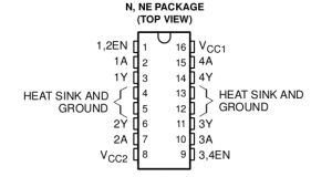
The following is the pin diagram of the IC.

l293d pinout

The following is the explanation for the different pins of the IC.

  • Vcc1 (pin 16) takes in regulated 5V for operating the IC.
  • Vcc2 (pin 8) takes the external voltage (up to 36V) which
  • 1,2 EN (pin 1) and 3,4 EN (pin 9) are the enable pins for the two motors
  • 1A (pin 2) and 2A (pin 7) are the control pins for Motor 1. These will be connected to Arduino.
  • 1Y (pin 3) and 2Y (pin 6) are the output pins for Motor 1. These will be connected to the first motor.
  • 3A (pin 10) and 4A (pin 15) are the control pins for Motor 2. These will be connected to Arduino.
  • 3Y (pin 11) and 4Y (pin 14) are the output pins for Motor 2. These will be connected to the second motor.
  • pins 4,5,12,13 are Gnd pins

Connecting H-bridge with Arduino

As I explained above, we will be connecting H-bridge to Arduino, using the following connection.

  • 1,2 EN (pin 1) goes to Arduino digital pin 10
  • 1A (pin 2) goes to Arduino digital pin 8
  • 2A (pin 7) goes to Arduino digital pin 9
  • 3,4 EN (pin 9) goes to Arduino digital pin 11
  • 3A (pin 10) goes to Arduino digital pin 12
  • 4A (pin 15) goes to Arduino digital pin 13
  • 1Y (pin 3) goes to one terminal of motor 1
  • 2Y (pin 6) goes to another terminal of motor 1
  • 3Y (pin 11) goes to one terminal of motor 2
  • 4Y (pin 14) goes to another terminal of motor 2
  • Vcc1 (pin 16) goes to 5V pin in Arduino.
  • Vcc2 (pin 8) should be connected to the +ve terminal of your battery.
  • Connect the -ve terminal of your battery to one of the Gnd pins (4,5,12 or 13)
  • Connect Gnd from Arduino to one of the Gnd pins (4,5,12 or 13)

Note: Apart from the two enable pins, you can connect other pins to any other digital pins in Arduino. Next week, I will explain why we should connect the enable pins to only pin 10 and 11. Also, we might need some small capacitors across the power lines to remove noise. I have not added them, to keep the circuit simple and easy to understand.

Controlling directions of DC Motors

As you can see from the above pin diagram, each motor has 3 pins (1 enable pin and 2 control pins) through which we can control the motor. The logic to control the direction of the motor is as follows.

  • If the enable pin for a motor is HIGH, then the motor will run.
  • If control pin 1 is HIGH and control pin 2 is LOW, then the motor will rotate in one direction.
  • If control pin 1 is LOW and control pin 2 is HIGH, then the motor will rotate in the other direction.
  • For all other cases, the motor will not run.

The logic can also be expressed in the following tabular form

Enable Pin Control Pin 1 Control Pin 2 Motor status
H H L Rotates in one direction
H L H Rotates in another direction
H H H Does not rotates
L Doesn’t matter Doesn’t matter Does not rotates

I have written a small Arduino sketch to explain this. You can find the full sketch at github.

This will rotate both the motors in one direction for 10 seconds and then will change their direction for the next 10 seconds.

Here’s a video of it.

Homework

What’s the fun in just doing what I am doing? After trying out this sample code, expand it to do the following

  • Run both motors in the same direction
  • Reverse the direction of both the motors
  • Run both motors in different direction
  • Stop one motor and run the other one.

Once you have completed any or all the above, let me know by posting a comment below or in twitter and include @hardwarefun.

What’s next

Next week we will see how we can control the speed of the motor. Also, I will talk about how we can abstract the code into a library so that we can reuse it every where.

Till then, happy roboting ๐Ÿ˜‰

Building Robots using Arduino – DC Motors

This is part 2 of my “Building Robots using Arduino” tutorial series, explaining how you can create robots using Arduino.

In this article, I will introduce DC motors and how to use them.

Types of Motors

If you look at the Wikipedia page of DC motors, you will realize that there are different types of DC motors. In this tutorial, I am going to be concentrate only on DC Brushed motors.

Parameters for choosing DC Motors

There are three different parameters that you have to keep in mind while choosing a DC motor for your project. They are

  • Voltage
  • RPM
  • Torque

Voltage

This parameter specifies the voltage level at which the motor will run. Most hobby motors work in the voltage range of 5-12 V. You should make sure that you don’t run the motor outside its range.

RPM

The next parameter to keep in mind is RPM (Rotations Per Minute). This basically specifies the number of rotations that will be made by the motor when the specified voltage is applied across its terminals. The higher the RPM, the faster the motor will run. Typical rpm’s for a hobby motor ranges from 200-2000 rpm.

Torque

The torque of a DC motor, specifies the force at which the motor will run. If the torque of a motor is high, then it can pull more load. You should choose the torque of the motor, based on the load/weight it has to pull.

Connecting a DC Motor

The DC motor will have two terminals.

If you connect the positive terminal of a battery/voltage source at one end and the Gnd at the other end, then the motor will rotate in one direction. If you reverse the connection, then the motor will run in the opposite direction.

Testing a DC Motor

We can do the following small experiment to better understand the connections of a DC motor.

Take a DC motor and a battery which has the voltage equal to the voltage rating of the DC motor. If no wires are soldered in the DC Motor, then take two pieces of wires and solder them at the two terminals.

Connect the positive terminal of the battery, to one terminal and the Gnd terminal of the battery to the other. You should see the motor rotating. Make a note of the direction of rotation.

Next reverse the terminals. The motor should rotate again. Make a note of the direction of rotation. If you have connected it properly, then you will notice that the direction of rotation has changed.

Connecting the motor to Arduino

Now let’s try to do the same thing using Arduino. To do that we have to simulate the positive and Gnd connections of a battery in Arduino.

Note: Don’t use a high voltage motor for this. This might spoil the Arduino board.

If you set a pin to output mode, and then put it in high state, then it is equal to the positive terminal of a battery, since it will be at +5V. Similarly, if you set a pin to output mode, and then put it inย low state, then it is equal to the Gnd terminal of a battery.

Let’s write a small Arduino sketch to test the motor.

In the above program, I set two pins (12 and 13) to be in output mode. After that, for the first 5 seconds I set pin 13 to be high and pin 12 to be low. So pin 13 will act as +ve terminal and pin 12 will act as ground. The motor will rotate in one direction.ย For the next 5 seconds, I set pin 13 to be low and pin 12 to be high. When I do that, the terminals are interchanged and the motor will rotate in the other direction.

You can see this in action in the following YouTube video.

This sketch is very similar to the led blink sketch. Remember what I said last week – if you can blink a led, you can build a robot as well ๐Ÿ˜‰

What’s next

As you might have already figured out, this method is not very efficient. Also you can’t supply full voltage to the motors. We will correct all that next week.

In the next post of the series, we will use an IC called L293D which will make our life a lot easier ๐Ÿ™‚ We will also see how we can change the speed of the motor, in addition to the direction.

See you all next week then. Till then happy roboting ๐Ÿ™‚

Building Robots using Arduino

I am starting a new series of articles explaining how you can create robots using Arduino. These are the same robots, that I used in my various talks.

I am planning to post the article every Friday, so that you will have enough time to try it out over the weekend.

Assumptions

I am going to assume, that you have basic knowledge of Arduino and electronics. If you can make LED’s blink, then you are ready ๐Ÿ˜‰

If not, you can use the following tutorials to get started. These were the same resources that I used when I started playing around with Arduino.

Soldering skill is not mandatory, but would be a plus. If you struggle with soldering (I still do ๐Ÿ™‚ ), then refer to the comics soldering book by Mighty Ohm.

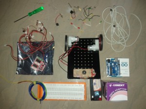
Parts needed

  • Any Arduino (Uno, Leanardo, Mega or one of the many clones) and the USB cablearduino-robotics-kit
  • 2 DC Motors (preferably 6V)
  • 12V Led acid battery and charger
  • Breadboard
  • Bot Chasis frame
  • 2 (or 4) Wheels
  • Front support wheel
  • Screws, Bolts & Screw driver
  • LED, Light sensors, resistors, jumper wires etc
  • L293D IC (preferably in a breakout board). You can also use a Motor shield if you have one

Agenda

The following is the rough agenda, that I am planning for this series. Based on the feedback, I might slightly tweaked it a bit.

  • Introduction & parts needed
  • Introduction to DC motors
  • Using L293D and controlling DC Motor speed
  • Assembling the bot
  • Putting everything together

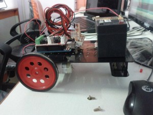
We will have a basic working bot by this time. It will look roughly like below.

arduino-robotics

After that I will teach you how to do cool stuff with the bot. Right now I am planning to do the following.

  • Teach it bot to avoid obstacles using IR
  • Find how far it is from obstacles using Ultra sound
  • Control the bot using your Android device
  • Control the bot from a browser

In addition if you want me to write a tutorial on a specific feature, then do let me know by leaving a comment below and I will try my best ๐Ÿ™‚

Happy Roboting ๐Ÿ˜‰

Arduino Yรบn – Arduino based wireless Linux board

I was following news about Maker Faire in Twitter today and was quite surprised when I came to know that Massimo Banzi co-founder of Arduino, announced Arduino Yรบn, a new product that combines Arduino and Linux.

Specification

I was quite excited and quickly checked the specs. It is a combination of Arduino Leonardo (based on the Atmega32U4 processor) with Atheros AR9331 a Wifi system-on-a-chip running Linino (a MIPS GNU/Linux-based on OpenWRT).

On the microcontroller level, it has 14 digital input/output pins (of which 7 can be used as PWM outputs and 12 as analog inputs), a 16 MHz crystal oscillator and a micro USB connector like Leonardo.

But in addition to that, it has a standard A type USB connector, a micro-SD card plug and is Wi-Fi enabled. I am not sure if the USB connector can be used in host mode. If yes, then it will be awesome.

Programming

One of the exiting features for me personally is that you can program this board using Wi-Fi. Also they provide a Bridge library that allows you to link the 32u4 microcontroller with Linux.

It seems that you can also SSH into the board and install custom Linux packages.

Cost

The cost of the board is $69 and will be available at the end of June.

How it compares with Raspberry Pi

Now the real question is how does it compare with Raspberry Pi. This seems to be the first question in the comments section of Arduino blog as well ๐Ÿ™‚

Okay, Raspberry Pi wins clearly from the cost perspective. $35 vs $69 ๐Ÿ™‚

But I think the real benefit would be from the ease of programming perspective. Even though Raspberry Pi provides a full stack, setting up everything and then programming it could be quite involved. From the looks of it the board with the Bridge library seems to be mostly plug-and-play.

Also it seems Arduino has partnered with a startup called Temboo to provide normalized access to 100+ APIs from a single point of contact.

It would be really interesting to see how this product matures. Also Arduino is hinting that this is the first in a family of products.

So will I buy one even though I own a bunch of Raspberry Pi’s? YES, definitely ๐Ÿ™‚

Update: Arduino is starting to write a couple of blog posts about the board. Make sure you don’t miss it. Also it will be available for purchase from September 10.

Update: Here is the video ofย Massimo Banzi showing off Arduino Yรบn

Enabling audio output even when HDMI output is enabled in Raspberry Pi

When I wrote about choosing the correct display cable for Raspberry Pi, I mentioned that you might face problems with getting audio, when you use a cheap HDMI to VGA converter, that doesn’t support audio.

Problem

I use this cheap HDMI to VGA converter which I bought from Amazon, which doesn’t support audio. I thought that I will use this converter to get video output and then get the audio output through the audio jacket.

But it turns out that Raspberry Pi, will shut down audio output in audio jacket, when HDMI output is enabled. Since my converter only supports video, I was not able to get audio output from my Pi.

Solution

I was poking around the Raspberry Pi config files and then found that it is possible to manually override the audio and video output devices. After some more research, I came across the following command which allows you to choose the output devices.

amixer cset numid=3 <n>

where n could be one of the following values

  • 0 – auto (automatically choose the audio output device, based on video output device. If HDMI is enabled then set hdmi as audio output else use audio jacket as audio output. This is the default behavior)
  • 1 – analog (Fore audio jacket as audio output device)
  • 2 – hdmi (Force HDMI as audio output device)

Now, to enable audio through the audio jacket, I ran the command with the following option.

amixer cset numid=3 1

This allowed the audio to be available in the audio jacket. I connected this to my speakers and now I am able to get the audio output as well.

Problem solved ๐Ÿ˜‰

A guide to choosing the correct display cable for Raspberry Pi

Composite cables

When I wrote about choosing the correct accessory for Raspberry Pi, I mentioned that choosing the display cable could get a little tricky. There are a lot of things to keep in mind and so I thought of writing a separate guide for choosing the correct display cable.

The following are the different scenario’s which you might encounter.

You have a HDMI capable display device

If you have bought your TV or monitor in the last year or two, chances are high that you already have a HDMI capable display device. If you have a HDMI capable device then all you need is a HDMI to HDMI cable and you should be good to go.

If you look closer you might already have a HDMI cable, which would have come with your device. If not you could buy one for around Rs. 500 in SP Road.

You have a composite video capable display device

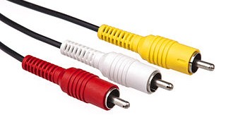
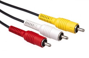
If you have a composite video capable device like a TV, then you can use a composite cable to connect Raspberry Pi with the device. The composite cable, also known as RCA connector consists of three plugs, one yellow, one white and one red (refer to the image below)

Composite cables

You have to connect the yellow lead (video) between Raspberry Pi and your device.

There are two small issues with RCA cables.

  • The resolution supported by Raspberry Pi through the composite cable connector is small.
  • You have to use a separate audio to composite cable converter to get audio.

You have a DVI-D capable device

If you have a device that has a DVI-D connector then you can buy a simple HDMI to DVI cable and use that to connect Raspberry Pi to your TV or monitor.

This works exactly like HDMI output and you should have any issues. You can get this cable for around Rs. 750 in SP Road.

DVI-D vs DVI-A vs DVI-I

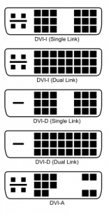
Once thing to note is that you must make sure that you have a DVI-D (digital) slot and not a DVI-A (analog) or a DVI-I slot. Compare your connector using the following diagram to figure out which one you have.

DVI-connector-types

DVI-D works by sending digital signals while DVI-A and DVI-I works by sending analog signals. They are not compatible with each other and Raspberry Pi supports only devices that have DVI-D slots.

You have only a VGA capable device

If you have a device that supports only VGA (like an old monitor or projectors), then things get little tricky, since Raspberry Pi doesn’t have support for VGA devices out of the box.

You might come across VGA to HDMI cables but these are used to convert VGA signals into HDMI signals and not the other way around.

There are a couple of HDMI to VGA converters available, but they are generally quite expensive and are not available in SP Road. The following are some adapters that are known to work.

  • Adafruit (expensive, but supports audio as well)
  • Amazon (supports only video, audio is not available through Pi’s audio jacket)

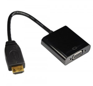
I bought the second one from Amazon and it looks like this.

hdmi-to-vga-adapter

It works with my very old VGA monitor, but the problem is that you don’t have audio support. Since HDMI output is enabled in Raspberry Pi, it shuts off the audio jacket.

Update: I found a way to enable audio output even when hdmi is enabled

Just use SSH

The last option is to just use SSH and connect to Raspberry Pi from a terminal. This of course needs your Pi to be connected to a network.

You can also install a VNC server in Raspberry Pi and use any VNC client to connect to it.

I was using this approach till I bought the HDMI to VGA converter.

I hope this guide helps you to choose a correct cable and display device for Raspberry Pi. If you have any more suggestion, feel free to leave a comment below.

Happy Pi’ing ๐Ÿ˜‰

A guide to choosing correct accessories for Raspberry Pi

raspberry pi up and running

Ever since I bought my Raspberry Pi, people reached out to me asking what are the accessories that I am using with it. It took me a bit of research to find out the best accessories needed for Raspberry Pi and I thought of documenting it so that it is useful for others as well.

Wherever possible, I will also include options to source them locally from SP road in Bangalore. Meanwhile, if you have any suggestion then do leave a comment below and I will update the post.

Power supply adapter

The first and foremost important accessory for Raspberry Pi is the power adapter. You need to be little careful while choosing this, because if you don’t give enough power to Raspberry Pi, then you will get random freezes and if you give too much power, you might burn your pi, which I guess you don’t want to do ๐Ÿ˜‰

You need an adapter that can give 5V and around 1.0A (1000 mA) to 2A (2000 mA). It should be on the higher side, if you are connecting lot of USB devices.

Before you decide toย buy a power adapter, do a quick look around. Chances are high for you to find one lying around in your home. Most mobile phone chargers work at 5V and can give around 1.0 A current.

I found that following to be working for me.

  • iPad charger (not iPhone charger)
  • HTC Hero mobile charger
  • Samsung Nexus phone charger
  • Kindle charger

If you are in Bangalore, then you can buy a good 5V 2A power adapter for around Rs. 300 in SP road.

Display cable

After the power supply, the next tricky one is choosing the proper display device and cable for your Raspberry Pi.

If you have a HDMI capable display device

If you have a HDMI capable TV or a monitor, then it is slightly easy for you. All you need to buy is the HDMI to HDMI cable and you are all set.

You most probably will have a cable that came with your TV or monitor. If you don’t have one lying around, you can buy it in SP road for around Rs. 500.

If you don’t have a HDMI capable display device

Things get little tricky if you don’t have a HDMI capable TV or monitor. I will write another article explaining the full list of options, meanwhile you can use the following guideline. Update: I have written a separate guide for choosing the correct display cable for Raspberry Pi.

If you have a TV or monitor that supports DVI-D (not DVI-A) then you can buy a HDMI to DVI cable. It costs around Rs. 750 in SP road.

If your device supports composite video-audio, like most old TV’s then you can use a composite video cable (yellow) to connect Raspberry Pi to your TV. But keep in mind that most of the timeย the quality of video and resolution is not that good.

If you have only a VGA supported device, like old monitors or projectors then you have to buy a HDMI to VGA converter (not cable). They are generally expensive and you don’t get them in SP road. Two options that I found to be working are the following.

The other option is to just use ssh and screen to communicate to your pi from a terminal. I was doing it till I bought the cable myself.

SD Card

The next accessory that you need to buy is a SD card. You need at least 2GB card to fit the default OS image. I would suggest you to get either a 4 GB or 8 GB one, because if you start to do anything important you need more space and storage these days are cheap. So an extra couple of hundred rupees is worth it.

One important thing to note is that you should buy one which is at least of class 4. A class of a SD card denotes the speed at which it can write and Raspberry Pi has issues if the class of the SD card is less than 4.

I bought a 16 GB class 4 Sandisk card for Rs. 750 in SP road. 8 GB ones cost around Rs. 500.

Sites like Adafruit sell preloaded cards and are generally a little costly. I wouldn’t recommend them, unless you are an absolute beginner and don’t want to load the OS into the card yourself.

SD Card reader (optional)

If you choose not to buy a preloaded card, then you need a card reader to connect your SD card to your computer. Most modern laptops and mac have a built-in card reader. If you don’t have one, then you might have to add that also to your list.

Wifi Dongle

If you have model A pi or if you don’t want to connect an ethernet cable in your model B pi, then you can buy a WiFI dongle. I bought mine from element 14 and it was working out of the box.

You can also buy one from SP road for around Rs. 900. There are cheaper ones available, but I am not sure whether they will work with Raspberry Pi.

Keyboard and mouse

You can connect any USB keyboard or mouse and it will work. But if you only have a PS2 keyboard or mouse, then you can buy a USB to PS2 converter for around Rs. 300 in SP road.

I would also recommend a wireless keyboard and mouse if you are going to be far away from your pi or use XMBC to make your pi as a media center.

USB thumb drive (optional)

Even though you can’t boot only from a USB thumb drive, I found that just having the boot partition in a SD card and the remaining file system in a USB thumb drive gives me slightly better performance. I Will write an article explaining the process soon.

So if you are planning to do this as well, then you might consider buying a 4 or 8 GB high speed pen drivers.

USB Hub

Since model B has only two USB slot (and model A has only one), you will be running out of USB slots pretty soon. To connect more devices you need to buy a USB Hub.

Also if the USB devices that you using requires a significant amount of power, then you might have to buy a powered USB hub.

The normal USB hub costs around Rs. 100 and the powered one around Rs 450 in SP road.

Case

I keep my pi on most of the time and found it prone to become dusty. I bought a case to protect it and would recommend it as well.

You can buy a fancy one for around $20 or buy a minimalistic one which is just functional. I bought mine for around $8 in Sparkfun.

Recently, I discovered that it is also available in SP road for around Rs. 300.

One thing to keep in mind while choosing the case is that, make sure it has an opening for the GPIO pins. I found that most fancy ones don’t have the opening and it becomes difficult to interface the pi with external devices.

I hope that this guide helps you to choose the correct accessory for your Pi. If you have any suggestion then leave a comment below and I will add it to the list.

Happy pi’ing ๐Ÿ˜‰

Calculating correct resistor value to protect Arduino pin

Ohms Law

Once of the important things to do when you play around with electronics is to make sure that you are safe-guarding your electronic components from over current.

The most common way to do that is by adding a resistor in series. You can calculate the value of the resistor needed for safe operation by using Ohm’s law.

But, when I was getting started with electronics and Arduino, I always found it difficult to understand how a particular value of resistor is recommended in tutorials, even though you will be getting a different value when you try to apply Ohm’s law yourself.

It took me quite sometime to understand the logic behind it and I thought of explaining it here, so that it is helpful for people who are also just getting started.

Protecting Arduino Pin from over current

Let’s consider the simple Blink example in Arduino. This is most probably the first program you might have tried when you are getting started with Arduino.

If you look at the circuit, you will find that you are asked to connect a 220 Ohm resistor in series to protect the Arduino pin and the LED. But it is not mentioned how or why this value is chosen.

Now let’s try to calculate the value ourself. You need to be familiar with Ohm’s law, if you are not, then read this excellent tutorial by Evil Mad Scientist, which explains the whole concept very clearly.

If you have read the above tutorial, you will now know that a typical red LED has a voltage drop of 1.8V and a current of about 25mA. The Arduino Pin has an output voltage of 5V.

Let’s use these values in our calculation.

V = (power source) – (voltage drop) = 5V – 1.8V = 3.2 V
I = 25 mA

We need to find R.

R = V/I

Substituting the values, you will get

R = 3.2/0.025 = 128 Ohms.

We need to use 128 Ohm resistor, but the tutorial asks us to use 220 Ohm, which is almost double.

Practical easiness over theoretical correctness

It took me quite sometime to figure out why 220 Ohm is recommended over 128 Ohm.

It is an apt example of choosing practical easiness over theoretical correctness. Engineers being practical people always prefer practical solutions over theoretical ones ๐Ÿ˜‰

If you try to buy resistors from a local hobby shop, you will find that the resistors are available in the following values.

{ 100, 220, 470, 1000, 2200, 4700, 10000 }

These are the standard values and are easier to find rather than other values.

If you look at the values, you will find that 100 Ohm is less than 128 Ohm (that we calculated) and is quite risky. The next higher easily available value is 220 Ohm.

When you substitute R=220 in the equation I=V/R

I = V/R
I = 3.2/220 ~= 14mA

You will get the value of the current to be around 14mA. LED’s operate between 10-25mA. Also, since LED’s are non-linear devices, the difference in the current from 14mA to 25mA doesn’t necessary mean a proportional difference in the brightness. In most cases, you may not even be able to tell the difference.

So, choosing 220 Ohm instead of 128 Ohm is purely because of practical easiness. If you have bought a getting started kit with Arduino or a pack of assorted set of resistors, you are more likely to find a 220 Ohm rather than 128 Ohm.

As, I mentioned before, the Blink example is most probably the first circuit that people are going to try and if you ask them to use a non-common resistor, then most probably they are not going to find it and might stop right there itself, instead of going forward. And that’s the reason why they have recommended 220 Ohm.

Arduino, being a platform for beginners, it is perfectly fine that they tried to simplify things for you. But once you start to grasp things, you might have to dig deeper to understand why a particular circuit or sketch is build in a certain way.

Happy hacking ๐Ÿ™‚