Monthly Archives: June 2013

Compiling Arduino sketches using Makefile

One of the main reasons why Arduino is very popular with beginners is that it is completely self-contained which makes it very easy to use. Once you have an Arduino board, all you have to do is to download the software and within minutes you can make your first led blink. The software has everything you need right from the IDE, to the compiler and even serial monitor to communicate with Arduino, all within one single package.

While the Arduino IDE is very good for beginners, you might start to feel its limitations, once you start working with it regularly. I use vim for everything and always wished writing Arduino sketches in vim.

I configured Arduino IDE, to use an external editor and started using vim to write code and then Arduino IDE to compile and upload. While this worked for sometime, I started to feel the need for a proper makefile so that I can do everything from vim itself.

Makefile for Arduino

My search landed me to a makefile created by Martin Oldfield. I started using it regularly and also contributed back my patches. Over a period of time, Martin lost interest in the project and now I took ownership of the project and maintain it.

The makefile is quite mature now and in most cases, you can use it to replace the Arduino IDE. There are still some corner cases, but I guess you may not hit them in your day to day use. Also the other advantage of using the makefile is that, you can even program directly using AVR C or assembly, which is not quite easy to do with the Arduino IDE.

Installation

The makefile requires the Arduino software to be installed. So if you have not installed it before, then you have to install it first.

There are three ways by which you can get the makefile

  • Install through package
  • Do a checkout from github
  • Download zip file from github

Install through package

Packages are available for Debian, Ubuntu and FreeBSD. The package name is arduino-mk. If you prefer to install a package, rather than checking out code from github, then you can install the package, if you are using Debian, Ubuntu or FreeBSD.

I also have plans to have a package for homebrew. I will post an update once the package is available for homebrew.

Do a checkout from github

The makefile is hosted in github. You can directly checkout from github. The advantage of this method is that it is every easy to get updates, since the project is currently under heavy development.

Download zip file from github

If you are not comfortable with git or don’t want to do a checkout, then you can also download the zip file from github.

Install dependencies

The Makefile delegates resetting the board to a short Perl program. You’ll need to install Device::SerialPort and YAML library.

On Debian or Ubuntu:

apt-get install libdevice-serialport-perl
apt-get install libyaml-perl

On Fedora:

yum install perl-Device-SerialPort
yum install perl-YAML

On Mac using MacPorts:

sudo port install p5-device-serialport
sudo port install p5-YAML

and use /opt/local/bin/perl5 instead of /usr/bin/perl

On other systems:

cpanm Device::SerialPort
cpanm YAML

Setup

Instead of copying the makefile to every sketch folder, you can just place the downloaded makefile separately in a common location and then create a small child makefile for every sketch.

Global variables

Once you have copied the makefile to a common location, or installed it through a package, you need to declare the following global variables. You can either declare them in your child makefile or set them as environmental variables.

  • ARDUINO_DIR – Directory where Arduino is installed
  • ARDMK_DIR – Directory where you have copied the makefile
  • AVR_TOOLS_DIR – Directory where avr tools are installed

I have the following setup in my ~/.bashrc file

export ARDUINO_DIR=/home/sudar/apps/arduino-1.0.5
export ARDMK_DIR=/home/sudar/Dropbox/code/Arduino-Makefile
export AVR_TOOLS_DIR=/usr

Per sketch variables

After the global settings, you will need to specify the following variables for each sketch

  • BOARD_TAG – The Arduino board that you are using. By default Uno is used
  • ARDUINO_PORT – The serial port where Arduino is connected
  • ARDUINO_LIBS – Space separated set of libraries that are used by your sketch

Usage

Compiling programs

To compile your programs you just have to invoke the command make.

The output is pretty verbose and will list down the configurations that the makefile is using and from where it got the values.

All the build files will be created under a subdirectory in your sketch folder.

If there were any errors then they will be displayed with line numbers, which you can correct.

Uploading programs

To upload the compiled program to your Arduino, just plug your Arduino and run the command make upload.

The program will be recompiled if needed and will be uploaded to your Arduino board.

Opening Serial monitor

The makefile can also be used to check the serial output from your Arduino. To do that just run the command make monitor.

This command will open a serial connection to your Arduino using screen.

The makefile tries to auto detect the baud rate. If it is not able to detect it properly, then you can manually set it using the variable MONITOR_BAUDRATE.

Advanced Usage

In addition to the above typical workflows, the makefile can also be used to do the following advanced stuff. I will write detailed guide for each of these use cases when I get some free time. Meanwhile you can also checkout some of the sample makefiles in the examples folder at github.

  • Compiling plain AVR C programs
  • Program using Arduino as ISP
  • Generate assembly and symbol files
  • Program using alternate Arduino core (like ATtiny or Arduino alternate cores)

Related projects

If you are using Vim as your editor for compiling Arduino programs then you might be interested in some of my following projects as well.

Do check them out as well ๐Ÿ™‚

Controlling speed of DC Motors using Arduino

This is part 4 of my “Building Robots using Arduino” tutorial series, explaining how you can create robots using Arduino.

In this article we will see how we can control the speed of the DC motor using Arduino.

Recap

Last week, I explained how we can control the direction of DC motors using the H-Bridge L293D IC.

This week we will see how we can control the speed of the motor as well using the IC. Also I will talk about how we can encapsulate the entire logic into an Arduino Library.

Analog Write

Before we go ahead, we need to know about analogWriteย function in Arduino.

In Arduino, the analogWrite function allows you to generate a PWM wave in a pin. If you have tried out the LED fade example in Arduino, then you already know how to use it. If not, then checkout the PWM tutorial from Arduino reference.

This function takes a value between 0 and 255 and doesn’t work on all pins in Arduino. In Arduino Uno, it works on pins 3, 5, 6, 9, 10 and 11.

Controlling Speed of DC Motors

To control the speed of the motor, all we need to do is to replace digitalWrite function on L293D enable pins to analogWrite. The speed of the motor depends on value that was passed to the analogWrite function. Remember the value can be between 0 and 255. If you pass 0, then the motor will stop and if you pass 255 then it will run at full speed. If you pass a value between 1 and 254, then the speed of the motor will vary accordingly.

Circuit

You can just reuse the same circuit from last week.

Remember, I asked you to connect the enable pins of H-bridge to pins 10 and 11 of Arduino. This is because pins 10 and 11 are PWM pins.

Code

You just have to replace the function digitalWrite with analogWrite in last weeks code. The value you pass to analogWrite function will decide the speed of the motor.

Here is the modified sketch that you can use to change the direction as well as the speed of the DC motors.

Library

I have encapsulated the logic of changing directions of DC motors in an Arduino library called DCMotorBot. The library is available in github from where you can download it.

Instead of setting the pins individually, you can call the following directions to change the direction of the motors. Check out the examples sketches inside the /examples folder of the library.

  • Start
  • Stop
  • MoveUp
  • MoveDown
  • TurnLeft
  • TurnRight

Note: I am still working on adding support for changing the speed(pwm) as well.

What’s next

Next week we will see how we can put together all we have learned so far and build a complete bot. It’s going to be existing, so don’t miss it ๐Ÿ˜‰

Till then, happy roboting ๐Ÿ˜‰

Creating Robots using Arduino – H-bridge

This is part 3 of my “Building Robots using Arduino” tutorial series, explaining how you can create robots using Arduino.

In this article, I will introduce the H-bridge IC L293D and we will also see how we can use it to control the speed of the motor.

Recap

Last week, I introduced DC Motors and explained how DC motor works and how we can connect it to Arduino.

Towards the end we also found that controlling DC motors directly using Arduino digital pin is not that efficient, since we can only give Arduino’s 5V to the motor.

H-bridge (L293D)

The basic problem in using Arduino’s digital pins to control the motor directly is that it is very difficult to reverse the voltage.

To overcome this, we can use a circuit called H-bridge, which enables a voltage to be applied across the motor in either direction. We can either build the circuit ourself or use a pre-built IC. L293D is one such IC which is commonly used as a H-bridge. There are also other IC’s like L298 etc, but in this tutorial, we will see how we can use L293D.

I will probably will cover the other IC’s some time later in a separate post.

Using H-bridge

If you look at the datasheet of L293D IC, you will find that we can control two motors simultaneously using the IC. Even though the IC operates at 5V, it can still give a higher voltage (up to 36V) to the motor.

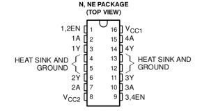
The following is the pin diagram of the IC.

l293d pinout

The following is the explanation for the different pins of the IC.

  • Vcc1 (pin 16) takes in regulated 5V for operating the IC.
  • Vcc2 (pin 8) takes the external voltage (up to 36V) which
  • 1,2 EN (pin 1) and 3,4 EN (pin 9) are the enable pins for the two motors
  • 1A (pin 2) and 2A (pin 7) are the control pins for Motor 1. These will be connected to Arduino.
  • 1Y (pin 3) and 2Y (pin 6) are the output pins for Motor 1. These will be connected to the first motor.
  • 3A (pin 10) and 4A (pin 15) are the control pins for Motor 2. These will be connected to Arduino.
  • 3Y (pin 11) and 4Y (pin 14) are the output pins for Motor 2. These will be connected to the second motor.
  • pins 4,5,12,13 are Gnd pins

Connecting H-bridge with Arduino

As I explained above, we will be connecting H-bridge to Arduino, using the following connection.

  • 1,2 EN (pin 1) goes to Arduino digital pin 10
  • 1A (pin 2) goes to Arduino digital pin 8
  • 2A (pin 7) goes to Arduino digital pin 9
  • 3,4 EN (pin 9) goes to Arduino digital pin 11
  • 3A (pin 10) goes to Arduino digital pin 12
  • 4A (pin 15) goes to Arduino digital pin 13
  • 1Y (pin 3) goes to one terminal of motor 1
  • 2Y (pin 6) goes to another terminal of motor 1
  • 3Y (pin 11) goes to one terminal of motor 2
  • 4Y (pin 14) goes to another terminal of motor 2
  • Vcc1 (pin 16) goes to 5V pin in Arduino.
  • Vcc2 (pin 8) should be connected to the +ve terminal of your battery.
  • Connect the -ve terminal of your battery to one of the Gnd pins (4,5,12 or 13)
  • Connect Gnd from Arduino to one of the Gnd pins (4,5,12 or 13)

Note: Apart from the two enable pins, you can connect other pins to any other digital pins in Arduino. Next week, I will explain why we should connect the enable pins to only pin 10 and 11. Also, we might need some small capacitors across the power lines to remove noise. I have not added them, to keep the circuit simple and easy to understand.

Controlling directions of DC Motors

As you can see from the above pin diagram, each motor has 3 pins (1 enable pin and 2 control pins) through which we can control the motor. The logic to control the direction of the motor is as follows.

  • If the enable pin for a motor is HIGH, then the motor will run.
  • If control pin 1 is HIGH and control pin 2 is LOW, then the motor will rotate in one direction.
  • If control pin 1 is LOW and control pin 2 is HIGH, then the motor will rotate in the other direction.
  • For all other cases, the motor will not run.

The logic can also be expressed in the following tabular form

Enable Pin Control Pin 1 Control Pin 2 Motor status
H H L Rotates in one direction
H L H Rotates in another direction
H H H Does not rotates
L Doesn’t matter Doesn’t matter Does not rotates

I have written a small Arduino sketch to explain this. You can find the full sketch at github.

This will rotate both the motors in one direction for 10 seconds and then will change their direction for the next 10 seconds.

Here’s a video of it.

Homework

What’s the fun in just doing what I am doing? After trying out this sample code, expand it to do the following

  • Run both motors in the same direction
  • Reverse the direction of both the motors
  • Run both motors in different direction
  • Stop one motor and run the other one.

Once you have completed any or all the above, let me know by posting a comment below or in twitter and include @hardwarefun.

What’s next

Next week we will see how we can control the speed of the motor. Also, I will talk about how we can abstract the code into a library so that we can reuse it every where.

Till then, happy roboting ๐Ÿ˜‰