This is part 3 of my “Building Robots using Arduino” tutorial series, explaining how you can create robots using Arduino.
In this article, I will introduce the H-bridge IC L293D and we will also see how we can use it to control the speed of the motor.
Recap
Last week, I introduced DC Motors and explained how DC motor works and how we can connect it to Arduino.
Towards the end we also found that controlling DC motors directly using Arduino digital pin is not that efficient, since we can only give Arduino’s 5V to the motor.
H-bridge (L293D)
The basic problem in using Arduino’s digital pins to control the motor directly is that it is very difficult to reverse the voltage.
To overcome this, we can use a circuit called H-bridge, which enables a voltage to be applied across the motor in either direction. We can either build the circuit ourself or use a pre-built IC. L293D is one such IC which is commonly used as a H-bridge. There are also other IC’s like L298 etc, but in this tutorial, we will see how we can use L293D.
I will probably will cover the other IC’s some time later in a separate post.
Using H-bridge
If you look at the datasheet of L293D IC, you will find that we can control two motors simultaneously using the IC. Even though the IC operates at 5V, it can still give a higher voltage (up to 36V) to the motor.
The following is the pin diagram of the IC.
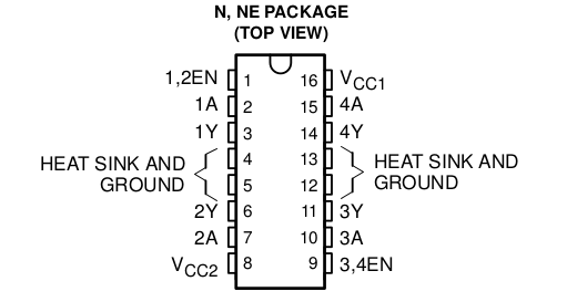
The following is the explanation for the different pins of the IC.
- Vcc1 (pin 16) takes in regulated 5V for operating the IC.
- Vcc2 (pin 8) takes the external voltage (up to 36V) which
- 1,2 EN (pin 1) and 3,4 EN (pin 9) are the enable pins for the two motors
- 1A (pin 2) and 2A (pin 7) are the control pins for Motor 1. These will be connected to Arduino.
- 1Y (pin 3) and 2Y (pin 6) are the output pins for Motor 1. These will be connected to the first motor.
- 3A (pin 10) and 4A (pin 15) are the control pins for Motor 2. These will be connected to Arduino.
- 3Y (pin 11) and 4Y (pin 14) are the output pins for Motor 2. These will be connected to the second motor.
- pins 4,5,12,13 are Gnd pins
Connecting H-bridge with Arduino
As I explained above, we will be connecting H-bridge to Arduino, using the following connection.

- 1,2 EN (pin 1) goes to Arduino digital pin 10
- 1A (pin 2) goes to Arduino digital pin 8
- 2A (pin 7) goes to Arduino digital pin 9
- 3,4 EN (pin 9) goes to Arduino digital pin 11
- 3A (pin 10) goes to Arduino digital pin 12
- 4A (pin 15) goes to Arduino digital pin 13
- 1Y (pin 3) goes to one terminal of motor 1
- 2Y (pin 6) goes to another terminal of motor 1
- 3Y (pin 11) goes to one terminal of motor 2
- 4Y (pin 14) goes to another terminal of motor 2
- Vcc1 (pin 16) goes to 5V pin in Arduino.
- Vcc2 (pin 8) should be connected to the +ve terminal of your battery.
- Connect the -ve terminal of your battery to one of the Gnd pins (4,5,12 or 13)
- Connect Gnd from Arduino to one of the Gnd pins (4,5,12 or 13)
Note: Apart from the two enable pins, you can connect other pins to any other digital pins in Arduino. Next week, I will explain why we should connect the enable pins to only pin 10 and 11. Also, we might need some small capacitors across the power lines to remove noise. I have not added them, to keep the circuit simple and easy to understand.
Controlling directions of DC Motors
As you can see from the above pin diagram, each motor has 3 pins (1 enable pin and 2 control pins) through which we can control the motor. The logic to control the direction of the motor is as follows.
- If the enable pin for a motor is HIGH, then the motor will run.
- If control pin 1 is HIGH and control pin 2 is LOW, then the motor will rotate in one direction.
- If control pin 1 is LOW and control pin 2 is HIGH, then the motor will rotate in the other direction.
- For all other cases, the motor will not run.
The logic can also be expressed in the following tabular form
| Enable Pin | Control Pin 1 | Control Pin 2 | Motor status |
|---|---|---|---|
| H | H | L | Rotates in one direction |
| H | L | H | Rotates in another direction |
| H | H | H | Does not rotates |
| L | Doesn’t matter | Doesn’t matter | Does not rotates |
I have written a small Arduino sketch to explain this. You can find the full sketch at github.
This will rotate both the motors in one direction for 10 seconds and then will change their direction for the next 10 seconds.
Here’s a video of it.
Homework
What’s the fun in just doing what I am doing? After trying out this sample code, expand it to do the following
- Run both motors in the same direction
- Reverse the direction of both the motors
- Run both motors in different direction
- Stop one motor and run the other one.
Once you have completed any or all the above, let me know by posting a comment below or in twitter and include @hardwarefun.
What’s next
Next week we will see how we can control the speed of the motor. Also, I will talk about how we can abstract the code into a library so that we can reuse it every where.
Till then, happy roboting 😉
hello master,,,how if i want to combine between sensor PING, motor dc, and arduino..? i hope you can replay my question..
Pingback: Controlling speed of DC Motors using ArduinoHardware Fun | Hardware Fun
Hey mate! Awsoem tutorials very handful 🙂
I was wondering if you could help me with a problem I’m working with on arduino.
I want to make the dc motors spin while using the vibration sensor! What I mean is, that I want the motors to start spinning after sending it a message with the help of the vibration sensor. do u know how I can link the arduino to do so? 🙂 thank you for your time.
Best regards
Jad Moussan
Hello Jad,
I am not sure if I understand your requirement completely. Can you explain it a bit more?
Pingback: Best article about H-bridge. | 空空如也
Where do you recommend the capacitors? in my project there is also a servo and it has now a horrible interference.
Yes. If you have lot of interference then you should add a capacitors.
Sir I am using l293D H bridge motor module with arduino.
You said the current which the bridge can output is around 36 V but I am getting 3-4V due to which the wheels of my car are not running fast enough, What can I do?
Please help.
Hi! Can you explain the funcion of the red lead that connects the positive battery (+9) to the Arduino pin Vin?
I dont understand why its connected.
Thanks!
Frank
Hello Frank,
The +ve terminal of the battery is connected to vin of Arduino so that it can be powered directly from battery.
Why is the Vin pin connected?
Is there a difference if all Ground pin are connected? I saw some tutorials where all Ground pins are connected.
I’m having some troubles in my projects and would like to understand what is going on there. I think the problem is on the Vin pin.
Thank you for the help
Oliver
Nice tutorial! However, I’m having a problem. When I connect Arduino via USB cable to power it, only 1 motor runs and after running properly for 1-2 seconds, the speed becomes slow. After 10 seconds, the motor stops and doesn’t run again even after 10 seconds. Any help on how to fix this? Thanks.
When you power an Arduino that is connected to a motor through USB, then you may not be able to get enough power to run the motor.
Try connecting an external power source for the motor for it to work properly.
Great tutorials very handful! ?
Nice diagram there… What if i put a sound sensor for it? how will i connect the wirings? and a little help for code maybe
That tutorial is brilliant!, thank you for that! Just a few things that I personally struggled with:
– My motor ran continuously in one direction at a slow speed and I couldn’t work out why. It turns out that every single ground pin of my SN75441ONE needed to be connected to ground (not floating), not just the one.
– It’s also ridiculously easy to fry your chip, so if it’s not working for you, check you pinouts make sense.
I wanted to share because this took me so long to figure out and it might help some other noob. Thanks again for the awesome tutorial 🙂