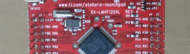
TI’s Stellaris LaunchPad board, which I reviewed recently comes with an out of the box demo program called qs-rgb. This program allows you to test the LaunchPad board and also try out some of the features of the LM4F120 MCU that is present in the board.
Getting the program into the board
When you buy the board, it comes pre-installed with the program and you don’t have to do anything. If you have already flashed another program into the board, then you have to re-flash the gs-rgb program, which you can find in the samples folder.
Powering the board

To run the demo program, you should connect the micro-B USB cable to the debug port of the board. The debug port is present at the top of the board. After connecting the cable, slide the slide switch towards right (You can find this switch at the top left corner of the board).
Once it is connected, power the board by connecting the A (large) side of the cable to a USB port on your computer.
Controlling the RGB LED
When you power on the board, the RGB LED (which is present in the right side of the board) will start to glow and will scroll through the color spectrum. If you press the left user button (present towards the bottom of the board, marked as SW1), then the LED will scroll towards the red end of the color spectrum. If you press the right user button (marked as SW2), then the LED will scroll towards the violet end of the color spectrum.
Testing out hibernation
The LM4F120 chip in the board supports hibernation mode and you can test it out as well. Press both the left and right user button together for 3 seconds and the MCU will go to hibernation mode. In the hibernation mode, the RGB LED will blink for 0.5 seconds for every 3 seconds with the last color.
You can press reset button to wake up the MCU.
Testing ICDI interface
The board comes with ICDI (In-circuit Debug Interface) and it provides a virtual serial port, through which we can communicate with the target processor. You can interface with the processor by connecting to this virtual serial port.
In Ubuntu you can find the virtual serial port by using the following command.
dmesg | grep tty
In my machine, it gave the following output
From this I know that the serial port is /dev/ttyACM0 in my machine.
If you are on Windows, I think you might have go to Device Manager to find the port.
Once you have identified the port, you can connect to it using terminal program like screen (or Putty if you are in Windows). While connecting you have to use the following configurations.
- baurd rate – 115200
- Data bits – 8
- Parity – None
- Stop bits – 1
I opened the virtual serial port using the following command
screen /dev/ttyACM0 115200
And then I pressed the reset button in the board to get the following prompt. You can type help to the list of available commands.
You can try out the listed commands as well, which allows you to control the RGB LED.
I am very impressed with the board so far and planning to start writing code for it soon. So stay tuned 🙂