I had a bunch of ATmega 16A and ATtiny 85 microcontrollers lying around and I was trying to find a way to program them using Arduino code. There are two main reasons, why I wanted to use Arduino code. The first reason was to use the many built-in functions like digitalWrite, digitalRead etc. And the second reason was to use the various built-in and user contributed Arduino libraries.
Since the official Arduino supports more than 3 types of microcontrollers (Uno, Mega, Leonardo), I had a hunch that supporting other microcontrollers should be easy. With this in mind, I started digging into Arduino code. After referring to couple of files inside the hardware folder, I found a way by which you can easily add support for non-Arduino AVR microcontrollers.
pins_arduino.h file
The developers of Arduino, have cleanly separated out the pin definitions into a separate files. This allows you to easily add support for new non-Arduino AVR microcontrollers.
To add support for ATmega 16A, I just copied the Uno’s pin_arduino.h file from hardware/arduino/variants/standard/ folder in Arduino installation directory and started modifying it.
In the pin_arduino.h file, you need to change the following things.
- The number of digital pins
- The number of analog pins
- Analog pin mappings and const for Analog pins (actual values for A0, A1)
- Digital pin to PCICR mapping
- Pin to port (PORTA, PORTB etc) mapping
- Pin to timer mapping
Most of these are straight forward and you can get the correct values from the target AVR chips datasheet. You can refer to the pin mapping file for ATmega 16A that I created.
boards.txt file
The Arduino IDE (and also my Arduino makefile) get details about your board from a file named boards.txt. This simple text file, has the details about your board and also instructs the Arduino IDE to use the proper parameters and fuses while compiling and uploading programs.
To let the Arduino IDE, know about our new microcontroller, we need to create a new boards.txt file which has the following information about the microcontroller.
- Upload protocol
- Upload speed (baudrate)
- Upload fuses
- Clock frequency
- Maximum flash memory size
- Which variant (
pins_arduino.h) file to use
Like the pins_arduino.h file, most of these are straight forward and you can get most of these details from the target AVR chips datasheet. You can refer to the boards.txt file, that I created for ATmega 16A.
Integration with Arduino IDE
Once we have created the pins_arduino.h and boards.txt file, we should then place them in a proper directory structure, which the Arduino IDE could understand.
First, create a directory called hardware in your sketchbook directory. After that create a new directory inside it to keep all our files. I named it arduino-extra-cores. Place the boards.txt file inside this directory. Now create a directory named variants and then create another directory with the name of your microcontroller. Place the pins_arduino.h file inside this directory.
Once you have done this, the directory structure should look like this.
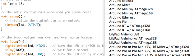
After doing this, restart your Arduino IDE and you should see the new entry that you created in the boards.txt file under the Boards menu, like below.
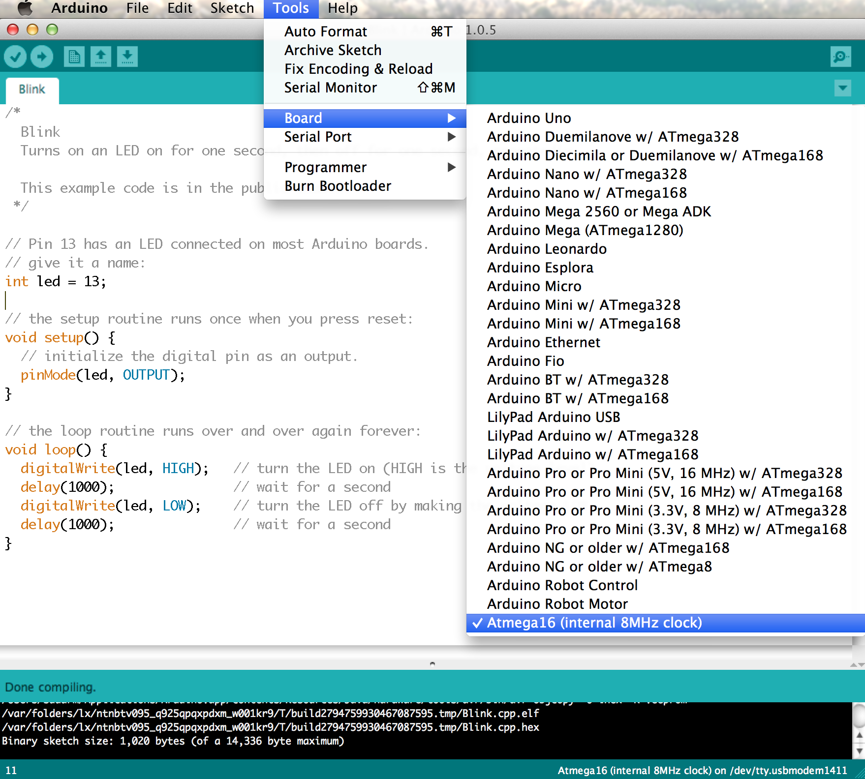
To compile and upload Arduino programs to your new microcontroller, you just have to select the new entry from the Boards menu, everything else will be taken care by the Arduino IDE.
If you don’t have a programmer to connect your microcontroller, you can also use an Arduino as a programmer to upload your programs. To use serial monitor, with your microcontroller, you can also use an Arduino as a bridge.
I have also written an separate tutorial that explains how you can use Arduino as an ISP programmer to program ATMega 16/16A micro controllers.
Arduino Extra Cores
I have put together all of this into a github repo called Arduino Extra Cores. Right now it supports both ATmega 16 and ATmega 16A family of microcontrollers. I am planning to support for more microcontrollers soon.
Feel free to check it out and also to use it as your template. If you managed to port a new microcontroller, I would be happy to merge it into my Arduino Extra Cores repo.
Happy Hack’ing 🙂
Update: Kindly note that this works only in Arduino 1.0.x branch. The structure of hardware folder has changed in Arduino 1.5.x branch and I have not updated the core yet to support it. Will post an update, once I had support for Arduino 1.5.x as well.
Nice! Just what I was looking for 🙂
Any idea why the 16A costs about 40% less than the 168?
Cheers
ff
Even I am not sure. In fact, 16A has more gpio pins than 168.
memory size, processing capabilities, pwm,adc pins might also matter
Hi,
This is too interesting, if it works.
I read some ‘To Do’ in your pins_arduino.h on line 40 from GitHub.
“//TODO: these are not assigned properly. Need to test more
#define digitalPinToPCICR(p) (((p) >= 0 && (p) <= 32) ? (&PCICR) : ((uint8_t *)0))
#define digitalPinToPCICRbit(p) (((p) <= 7) ? 2 : (((p) <= 13) ? 0 : 1))
…………………………………………
"
I am a beginner. I just need 40 to 44 lines explanation?
Can you help me?
Try it out. It should definitely work.
While I was porting the pins_arduino.h file, I found that Arduino also defines some macros which contain the mapping between digital Pin and PCICR interrupts. But while searching for it in the entire Arduino codebase, I found that it was not getting used anywhere. That is the reason for the TODO that I added.
I’ve got a breakout board for the Atmega1281, http://www.elecfreaks.com/store/bare-pcb-atmega128-smallest-system-board-p-137.html. The old Adruino Mega was based on the Atmega1280 (which has 100 pins compared to the 64-pin 1281). I had read somewhere that with the latest IDE that just modifying the pins_arduino.h and boards.txt was enough, is that true?
Yes, you can do it by adding a new pins_arduino.h and boards.txt file.
If you want to directly program it from IDE, without any external programmer, then you might have to add new bootloader as well.
Hi Sudar!
This is exactly the kind of info I was looking for, thank you!
I want to share a link that I found, it helps to calculate the fuses for almost every atmega
http://www.engbedded.com/fusecalc
Just one question: What do i have to modify if my atmega chip has no bootloader? I have an atmega16A-PU, without bootloader and an external programmer which I connect to a development board for 40 pins atmega (16 and 32)
Thanks in advance!
Enrique
Nice to know that you like it 🙂
If you are using an external programmer, then you don’t have to burn the bootloader or make any changes.
Here again…
Imtrying to upload the Blink code, and get this error message:
In file included from C:ARDUINOhardwarearduinocoresarduino/Arduino.h:213,
from Blink.ino:10:
C:ARDUINOhardwarearduinocoresarduino/pins_arduino.h:9: error: stray ‘302’ in program
C:ARDUINOhardwarearduinocoresarduino/pins_arduino.h:9: error: stray ‘267’ in program
C:ARDUINOhardwarearduinocoresarduino/pins_arduino.h:9: error: stray ‘302’ in program
C:ARDUINOhardwarearduinocoresarduino/pins_arduino.h:9: error: stray ‘267’ in program
C:ARDUINOhardwarearduinocoresarduino/pins_arduino.h:659: error: stray ‘#’ in program
C:ARDUINOhardwarearduinocoresarduino/pins_arduino.h:659: error: stray ‘#’ in program
C:ARDUINOhardwarearduinocoresarduino/pins_arduino.h:659: error: stray ‘#’ in program
C:ARDUINOhardwarearduinocoresarduino/pins_arduino.h:659: error: stray ‘#’ in program
C:ARDUINOhardwarearduinocoresarduino/pins_arduino.h:659: error: stray ‘#’ in program
C:ARDUINOhardwarearduinocoresarduino/pins_arduino.h:659: error: stray ‘#’ in program
C:ARDUINOhardwarearduinocoresarduino/pins_arduino.h:659: error: stray ‘#’ in program
C:ARDUINOhardwarearduinocoresarduino/pins_arduino.h:4: error: expected unqualified-id before ‘<' token
C:ARDUINOhardwarearduinocoresarduino/pins_arduino.h:659: error: expected constructor, destructor, or type conversion before '/' token
C:ARDUINOhardwarearduinocoresarduino/pins_arduino.h:659: error: expected unqualified-id before '<' token
C:ARDUINOhardwarearduinocoresarduino/pins_arduino.h:659: error: expected unqualified-id before numeric constant
C:ARDUINOhardwarearduinocoresarduino/pins_arduino.h:659: error: expected unqualified-id before '<' token
C:ARDUINOhardwarearduinocoresarduino/pins_arduino.h:659: error: expected unqualified-id before '<' token
C:ARDUINOhardwarearduinocoresarduino/pins_arduino.h:659: error: expected unqualified-id before '<' token
C:ARDUINOhardwarearduinocoresarduino/pins_arduino.h:659: error: expected unqualified-id before '<' token
C:ARDUINOhardwarearduinocoresarduino/pins_arduino.h:659: error: expected unqualified-id before '<' token
C:ARDUINOhardwarearduinocoresarduino/pins_arduino.h:659: error: expected unqualified-id before '<' token
C:ARDUINOhardwarearduinocoresarduino/pins_arduino.h:659: error: expected unqualified-id before '<' token
C:ARDUINOhardwarearduinocoresarduino/pins_arduino.h:703: error: expected unqualified-id before numeric constant
There are some stray characters in your source file. Check http://stackoverflow.com/questions/16649105/error-stray-302-in-program-codeblocks
hola como esta, estoy tratando de montar el proceso que explica, pero me da error de que no encuentra el COM aasignado y el id no deja configurar el puerto cuando conecto mi USBasp, me puede ayudar?
Hi Sudar!
Thanks for your help!
Now I have this message:
avrdude: warning: cannot set sck period. please check for usbasp firmware update.
Ive updated the firmware, but I still get that error
Can you give some additional information like the following
Im using an Atmega16A-PU powered with a 9V battery. Im using a USB-ASP programmer, with no external crystal oscillator.
I have selected the board in the menu
I’ve succesfully uploaded the sketch (the Blink example), but the chip runs eight times slower than expected (i.e. the blink sketch make the led on and off every 8 seconds)
What am I doing wrong?
Thanks for your help!
Sorry, I meant:
“Im using an Atmega16A-PU powered with a 9V battery. with no external crystal oscillator.
Im using a USB-ASP programmer,
I have selected the “Atmega16 (internal 8Mhz clock)” board in the menu”
Can you check the fuse settings? I guess for some reason the fuse bits are set to run at 1MHz
I have this in the boards definition
##############################################################
# Additional definitions for Arduino
# Author: Sudar
##############################################################
atmega16-8.name=Atmega16 (internal 8MHz clock)
atmega16-8.upload.protocol=stk500v2
atmega16-8.upload.maximum_size=14336
atmega16-8.upload.speed=57600
# TODO: Assign proper fuse values
#atmega16-8.bootloader.low_fuses=0xE4
#atmega16-8.bootloader.high_fuses=0x98
#atmega16-8.bootloader.extended_fuses=0xFF
#atmega16-8.bootloader.unlock_bits=0x3F
#atmega16-8.bootloader.lock_bits=0x0F
atmega16-8.build.mcu=atmega16
atmega16-8.build.f_cpu=8000000L
atmega16-8.build.core=arduino:arduino
atmega16-8.build.variant=mega16
##############################################################
# TODO: Add definitions for ATmega 16MHz
# TODO: Add definitions for ATmega external clock
Now I realize that maybe the fuses are just taking the default setting, so the chip runs at 1Mhz, as you said
Which is the right setting for the Atmega16A-PU fuses, with no bootloader and int 8 Mhz clock?
You can find the correct fuse settings from here http://www.engbedded.com/fusecalc
Hi Sudar
I looked for the correct fuse settings, and tried different settings, but I still have the same problem. The blink example is running at 1Mhz
Any ideas?
This is great information!
What about Atmega128?
If I want to change my pins definition for this micro where can I find information about pins_arduino.h file modification?
Jorge, where are you from?
Hablas español?
Olá Enrique,
I’m Portuguese. I understand Spanish as well but not to write I’m affaid :/
Atmega 128 is compatible with 328 used in Uno. So you don’t have to change anything if you want to use the same pins as Arduino Uno.
But if you want to change the pin definitions, then you can follow the same process like above and change the pins_arduino.h file.
Sudar, thanks for you comments.
ATmega128 has a lot more ports than 328 and to use them all (all pins) I have to change the pins_arduino.h file don’t I?
My main difficulty is to change pins_arduino.h file because I do not know how the definitions work out.
I’ve made a test sketch for check in witch I/O pin would correspond to the sketch instruction but I realized that actually the IO pins are shifted from my program instructions.
So I think it has to be something wrong with my pins_arduino.h file that I’m using from BREADUINO ATmega128 project .
Like, how does this instructions work?
const uint8_t PROGMEM digital_pin_to_bit_mask_PGM[] = {
// PIN IN PORT
// ——————————————-
_BV( 0 ) , // PE 0 ** 0 ** USART0_RX
_BV( 1 ) , // PE 1 ** 1 ** USART0_TX
_BV( 2 ) , // PE 2 ** 2 ** D2
_BV( 3 ) , // PE 3 ** 3 ** PWM3
Or this ones:
const uint8_t PROGMEM digital_pin_to_port_PGM[] = {
// PORTLIST
// ——————————————-
0 , // PEN
PE , // PE 0 ** 0 ** USART0_RX
PE , // PE 1 ** 1 ** USART0_TX
PE , // PE 2 ** 2 ** D2
Is there any literature where I can find this information?
Apart from the comments in the code there weren’t any other documentation available unfortunately 🙁
Yes. It is really difficult to find good and well explained information about this theme.
I have found after a lot of googling this site from Garret http://garretlab.web.fc2.com/en/index.html. It does help although is far from complete.
Hi Sudar.
First of all, congratulations you have done a nice job with this tutorial. i would like to know if you can you tell me the procedure to program a atmega16a using arduino RV3 as programmer, and the conections needed.
I really apreciate your help.
thank you.
i apologize about my grammar
Just give me a couple of days. I will write a detailed post on that.
ok, we will be waiting… thanks a lot.
I just wrote a tutorial explaining how you can use Arduino as a programmer to program ATMega 16/16A. Check it out at http://hardwarefun.com/tutorials/use-arduino-as-an-isp-programmer-to-program-non-arduino-avr-microcontrollers
thanks you Sudar i will check it out and comment.
Best regards.
Thanks for sharing. Very useful. Is it possible to add support for the Attiny26 family (261,461,861)
Adding support for other AVR’s should be relatively easy. Unfortunately, I don’t have one of those IC’s with me to port it 🙁
Hi,
If you can give me a hint where to start I can give it a try ?
I have found support for Attiny25,45 and 85 , 8 pin with A/D converter.
May this can be used as a starting point or template ?
What do you think ?
regards,
Ola
You need to create a new pins_arduino.h file and modify the pin definitions.
Yes you can use it as a template. Also checkout https://github.com/damellis/attiny
Hi,
I just recalled that some time ago I read that Arduinolite has support for the Attiny26, a bit “old” chip and more expensive that the newer Attiny261,461 and 861. 2,4,8 k flash memory.
Arduinolite also produces smaller and faster code than the standard Arduino sw. It seems that I have some plans for the weekend…
Ola
thanks so much..appreciable post.
Can u tell me how can i set the clock frequency to 16Mhz(external) ??
reply me
You need to set the proper fuse. You can calculate the fuse settings from http://www.engbedded.com/fusecalc
Pingback: Use Arduino as an ISP programmer to program non-Arduino AVR microcontrollersHardware Fun | Hardware Fun
Hi, sorry I’m trying on to ATmega16A TFQN that have 44 pin but…(maybe) if I starting numberation from 40th and jump on 17 and 18 I can obtain same result?
In specific I can’t programming LiquidCrystal lcd(RS, E, D4, D5, D6, D7); with correct pin number!
:-O
Hi Sudar
I added a board for an Atmega16A with 16 Mhz external crystal to the boards.txt file.
I copied your settings, and modified the fuses for matching the clock frequency, but the new board is not listed in the arduino IDE when I try to select it.
This is what Ive added to the boards list:
##############################################################
# Definitions for ATmega16 external 16MHz
##############################################################
atmega16-16.name=Atmega16 (external 16MHz clock)
atmega16-16.upload.protocol=usbasp
atmega16-16.upload.maximum_size=14336
atmega16-16.upload.speed=19200
atmega16-16.bootloader.low_fuses=0x9F
atmega16-16.bootloader.high_fuses=0x99
atmega16-16.build.mcu=atmega16
atmega16-16.build.f_cpu=16000000L
atmega16-16.build.core=arduino:arduino
atmega16-16.build.variant=mega16
Could you help me to solve this, please?
Thanks!
I found that hex file can not be run ok over 7168KB .
Which microcontroller are you using?
MEGA16
hi ,
sir I have done as per your tutorial the programme has successfully uploaded to my microcontroller but not giving any output from my atmega 16 microcontroller .could u plz help me.
thanks in advance.
You have to tell me what you tried and the code that you used. Without that it may not be possible for me to help you debug the issue.
if i want to program an atmega328, will i select tools>board>arduino uno?
Could it work with an atmega328 smd as well?
Thanks.
I think it should work. Have you tried it?
Hello
I’d like to use the attiny261 and i followed your steps. However i constantly get these conflicting errors:
In file included from /home/e-guy/.apps/arduino/hardware/arduino/cores/arduino/Arduino.h:235,
from /home/e-guy/.apps/arduino/hardware/arduino/cores/arduino/wiring_private.h:33,
from /home/e-guy/.apps/arduino/hardware/arduino/cores/arduino/wiring_digital.c:28:
/home/e-guy/.apps/arduino/hardware/arduino-extra-cores/variants/tiny20x61/pins_arduino.h:104: error: conflicting types for ‘port_to_output_PGM’
/home/e-guy/.apps/arduino/hardware/arduino/cores/arduino/Arduino.h:151: error: previous declaration of ‘port_to_output_PGM’ was here
what can i do?
HI sudar,
what you have done is awesome,,
but i wanted program ATtiny45,and ATtiny85 with arduino ide,please help out with pins_arduino.h file,and
pins_arduino.h file…or if u already modified for any of above two microcontroller i have mentioned….please please upload it…
Hello Shrikant,
To program ATtiny devices from Arduino IDE you need an alternate core. You can get one from https://github.com/damellis/attiny
thank you for your efforts
i used your files with Atmega16 in proteus but there is a shift in pin mapping for example if i coded pin22 to be output high it output high on pin 28
Hi Sudar
can i write Instructable from your post?
i think this is usefull post to share
and i really thanks for your help
now i have my homemade Arduino 🙂
Ekky,
Sure. But if possible do place a link in your instructable to this post.
Can u explain how will u use 16*2 lcd with atmega 16 using arduino ide,I mean pin connection etc.
This is a very insightful tutorial..thank you for it. please I would like to know if it is possible to add non atmel microcontrollers say nxp’s that are based on ARM architecture
Yes it is possible. For example checkout Energia that allows you to run Arduino code in TI’s boards.
But it may not be very easy to do and you may be need a project like Energia that provides the required Arduino cores for NXP.
thank you..i will check it out
hello, can i use the same code for ATMEGA32
I think you should be able to use it. Try it out and let me know if you face any issues.
Hello Sudar,
which arduino bootloader i can use in the ATMEGA16A ?
I didn’t use any bootloader for Atmega 16A, instead I just used the alternate core I mentioned.
I faced two problems. When I used the upload using programmer tool. It gave me an error saying upload.tool not found.
Also I don’t really understand how to upload the code. All the connections have been made. Do I need to burn the bootloader?
Your guidance is appreciated
To upload the programmer you would either need to load the bootloader on to the microcontroller or would require a programmer.
If you don’t have a programmer then you can use another Arduino as a programmer by loading the Arduino ISP sketch.
What is the alternate core that you mentioned?
I am using this alternate core – https://github.com/sudar/arduino-extra-cores
Pingback: ATmega32 and Arduino | Proof of concepts and advice
Hey Sudar,
Thank you very much this thing worked for me. I even made it work with an external 12Mhz external crystal.
Thank you very very much. This solution solved a big problem for me 🙂
Regards,
Sarang
Glad to know that you got it working 🙂
ini error kira2 kenapa gan?
:0:21: warning: missing whitespace after the macro name [enabled by default]
sama
Error while uploading: missing ‘upload.params.quiet’ configuration parameter
thanks.
I have problem with serial connection with my Atmega16. Usual Arduino command and libraries are working. Serial connection doesn’t work properly (I tried more baud rates and nothing). Then I tried to use SoftwareSerial, but theres a compiling problem:
C:\Program Files (x86)\Arduino\hardware\arduino\avr\libraries\SoftwareSerial\SoftwareSerial.cpp: In member function ‘void SoftwareSerial::begin(long int)’:
C:\Program Files (x86)\Arduino\hardware\arduino\avr\variants\ATmega16/pins_arduino.h:64:62: error: ‘PCICR’ was not declared in this scope
#define digitalPinToPCICR(p) (((p) >= 0 && (p) <= 32) ? (&PCICR) : ((uint8_t *)0))
^
C:\Program Files (x86)\Arduino\hardware\arduino\avr\libraries\SoftwareSerial\SoftwareSerial.cpp:319:7: note: in expansion of macro 'digitalPinToPCICR'
if (digitalPinToPCICR(_receivePin)) {
^
C:\Program Files (x86)\Arduino\hardware\arduino\avr\variants\ATmega16/pins_arduino.h:66:49: error: 'PCMSK2' was not declared in this scope
#define digitalPinToPCMSK(p) (((p) <= 7) ? (&PCMSK2) : (((p) <= 13) ? (&PCMSK0) : (((p) <= 21) ? (&PCMSK1) : ((uint8_t *)0))))
^
C:\Program Files (x86)\Arduino\hardware\arduino\avr\libraries\SoftwareSerial\SoftwareSerial.cpp:363:22: note: in expansion of macro 'digitalPinToPCMSK'
_pcint_maskreg = digitalPinToPCMSK(_receivePin);
^
C:\Program Files (x86)\Arduino\hardware\arduino\avr\variants\ATmega16/pins_arduino.h:66:76: error: 'PCMSK0' was not declared in this scope
#define digitalPinToPCMSK(p) (((p) <= 7) ? (&PCMSK2) : (((p) <= 13) ? (&PCMSK0) : (((p) <= 21) ? (&PCMSK1) : ((uint8_t *)0))))
^
C:\Program Files (x86)\Arduino\hardware\arduino\avr\libraries\SoftwareSerial\SoftwareSerial.cpp:363:22: note: in expansion of macro 'digitalPinToPCMSK'
_pcint_maskreg = digitalPinToPCMSK(_receivePin);
^
C:\Program Files (x86)\Arduino\hardware\arduino\avr\variants\ATmega16/pins_arduino.h:66:103: error: 'PCMSK1' was not declared in this scope
#define digitalPinToPCMSK(p) (((p) <= 7) ? (&PCMSK2) : (((p) <= 13) ? (&PCMSK0) : (((p) <= 21) ? (&PCMSK1) : ((uint8_t *)0))))
^
C:\Program Files (x86)\Arduino\hardware\arduino\avr\libraries\SoftwareSerial\SoftwareSerial.cpp:363:22: note: in expansion of macro 'digitalPinToPCMSK'
_pcint_maskreg = digitalPinToPCMSK(_receivePin);
^
it won’t compile for softwareserial library since Atmega16A does not support PCINT and softwareserial lib needs it.
best option would be to disable softwareserial lib compilation for Atmega16A 🙂
i m using atmega 16 with arduino ide.
but the genrated code by arduino doest work.
so pls tell me what’s wrong with it..
Imho It’s better to use avr libc instead of arduino sdk.
Hi, it worked to me, what kind of problema do you have?, are you able to upload your code?, please give us more details
I don’t know how much you like Arduino ide.
if you like cmake and linux,
you could use my https://github.com/amitesh-singh/amiduino/tree/master/avr/ami-atmega16-cmake
and build atmega16a sketches using Arduino SDK. 🙂
i have an arduino mega2560 and i want to use arduino code in atmega16 ,should i change any things that you creat like board.txt or pins_arduino.h?
Hello mr. sudar. such a good tutorial you have created here. i have a question btw, i want to use an external crystall (16Mhz) for my atmega16, so i changed the low fuse to “D9” and the high fuse to “FF”, and i modified the f_cpu to 16000000. am doing it right here to make the ext crystall recognized by the chip?? im looking forward to your answer. thank you
Looks like you are doing it correctly. Did it work?
Thank You Sudar
Now i just started with arduino.
I have run its all peripheral.
but now i want to make my own board with another AVR controller which is not available in arduino IDE then how to download boot loader in controller.
Hi,
Please add the tutorial for atmega32 ………….
Thanks
I have very little coding experience (get more!) but am interested in converting existing 8 bit open source code for 3d printers running 8-bit atmega code to 32 bit code. With proper attribution and open source results. If no real advantage of the new hardware is really taken, but just essentially the exact same code, but with proper pinouts and board mappings having been defined, is it possible to recompile the code from say the latest version of marlin, to make a 32 bit version of the same? How would you approach this and with what tools? I know the resulting code would not likely be issue free, but I hate the fact that the huge installed code base of work is 8-bit, when 32 bit boards are almost as cheap these days. If the code could be forked and ported enough times, we could all be using better boards sooner than later. You seem to have gone further down the trail on a Rosa I have been thinking of in the IDE environment
Iam Having Lcd connection hello world program for ATMEGA328p Audrino, now i need to work it in other board devloped by me. Please let me know in detail Iam stucked
dude i have done all the things as it is given.but when i select the board it says ” The current selected board needs the core ‘arduino:arduino’ that is not installed”
Can I use this method for my micro Atmega169PA???
hi,
very helpful post. but i am looking for the way around, that is, how we can use arduino library for atmega32 and other AVR mcu?