After reading my recent tutorial on using Arduino code in non-Arduino microcontrollers, one of my readers asked me if it is possible to use Arduino as an ISP programmer to program these micro controllers, instead of using a separate dedicated AVR programmer.
The answer is a definite yes and I use it all the time, since I have a lot of Arduinos lying around. I thought of writing a tutorial, so that it will be useful for others who want to do this.
In this tutorial, I will show how you can program a non-Arduino AVR microcontroller like AtMega 16/16A using Arduino as an ISP programmer.
Loading Arduino ISP sketch
By default Arduino IDE comes with an ISP sketch. All you need to do is to open it up in your Arduino IDE (or using my Arduino makefile), then connect your Arduino to your computer and then upload the sketch to your Arduino.
You should not connect anything else to your Arduino at this point and you will find the Arduino ISP sketch in File -> Examples -> ArduinoISP
Installing Arduino core for your microcontroller
The next step is to find the Arduino core support for the microcontroller you want to program and then install it.
If you want program ATMega 16/16A, then you can use my “Arduino extra core“. I have also written a separate tutorial explaining how to use it. Or if you want to program ATtiny microcontrollers, then you can use the ATtiny core by David Mellis, one of the co-founders of Arduino.
Most of the time, you just have to place these core files inside /hardware directory in your sketchbook folder, but consult the documentation of the actual core library you are using.
Connect the circuit
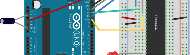
The next step is to connect the microcontroller to your Arduino. The below diagram shows how to connect ATMega 16/16A. In general the principle remains the same for other micro controllers as well.
Program ATMega 16 using Arduino as ISP Programmer
The following are the different pin connections
- Arduino Pin 13 to ATMega 16 Pin 8 (or SCK of another microcontroller)
- Arduino Pin 12 to ATMega 16 Pin 7 (or MISO of another microcontroller)
- Arduino Pin 11 to ATMega 16 Pin 6 (or MOSI of another microcontroller)
- Arduino Pin 10 to ATMega 16 Pin 9 (or RESET of another microcontroller)
- Arduino 5+ to ATMega 16 Pin 10 (or Vcc of another microcontroller)
- Arduino Gnd to ATMega 16 Pin 11 (or Gnd of another microcontroller)
- 10 uF capacitor between Arduino Reset Pin and Gnd Pin (+ve leg of capacitor should go to Reset pin)
- LED through proper resistor on any pin of the microcontroller, which you will be controlling through code
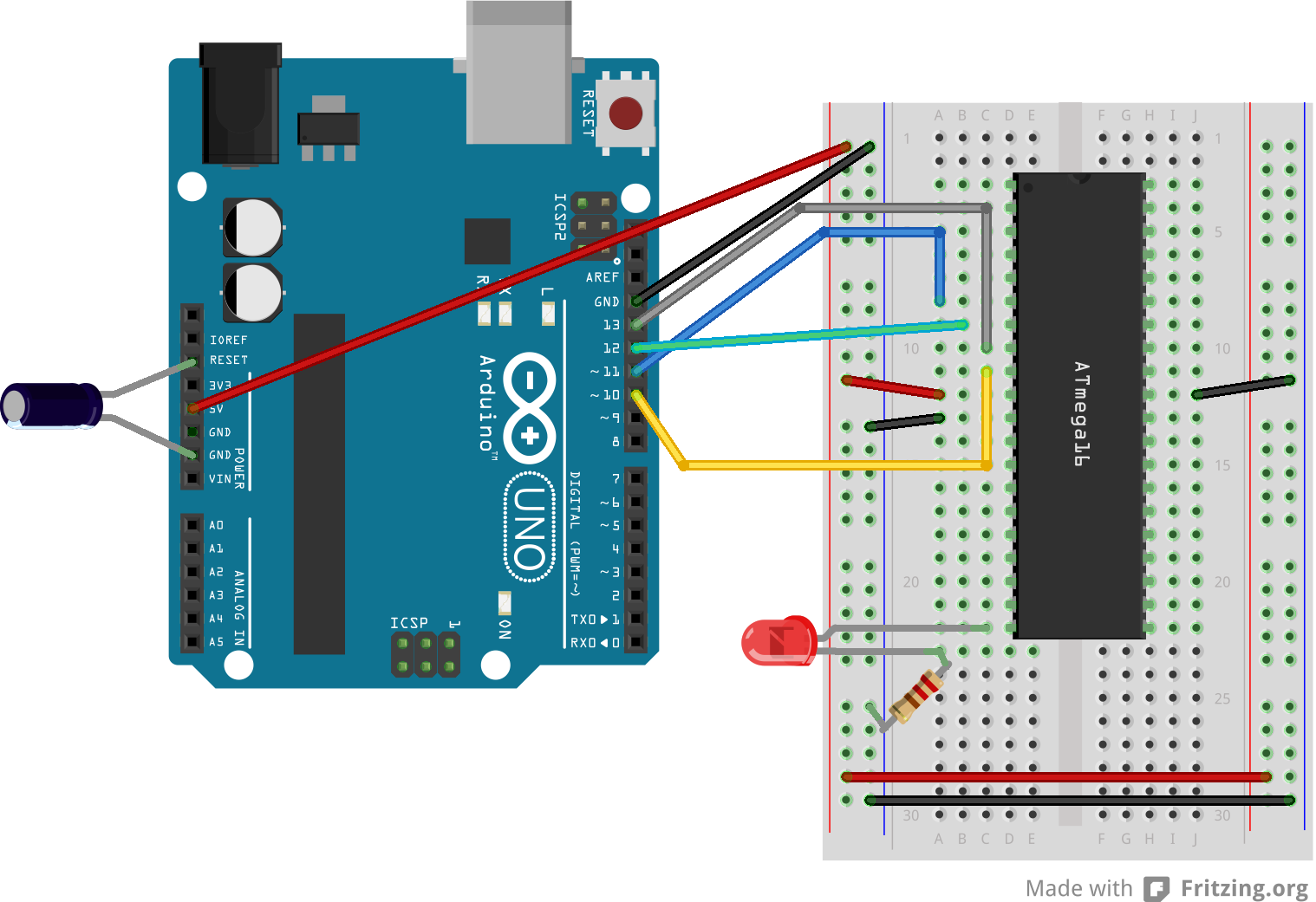
This is how my connection looks like
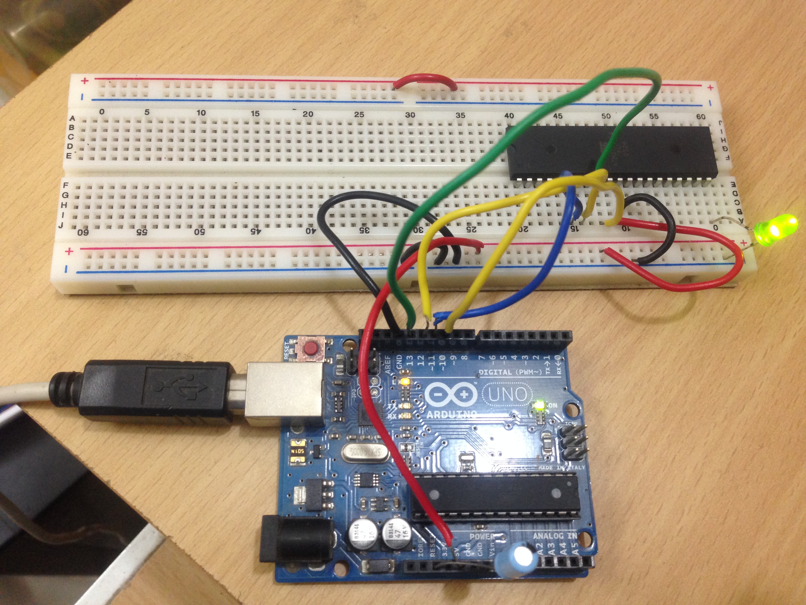
Program ATMega 16 using Arduino as ISP Programmer
Burn bootloader/fuse
The next step is to burn the bootloader or/and fuses. For most cores, you don’t need to use the bootloader.
My Arduino extra core doesn’t need any bootloader, but only needs some fuses to be set.
You can burn the bootloader and/or the fuses, by selecting Tools -> Burn Bootloader. Make sure you have chosen the correct board type before you do that.
Upload your sketch
Now, everything is ready, and all you need to do is to write your sketch and then upload it. The ISP sketch that your burned into your Arduino, will take care of the rest.
To use serial monitor, with your microcontroller, you can use my other tutorial which shows how you can use another Arduino as a bridge.
Upload your sketch using makefile
My Arduino makefile also supports uploading sketches through Arduino ISP programmer. Follow all the normal instructions and then define ALTERNATE_CORE and ISP_PORT in your makefile and run make ispload target.
Happy Hacking 😉
Hi Sudar, i followed the steps and i finally could upload my sketche, Thank you.
Do you know the reason why four of my new atmega16A chips don´t work the digital pins 18,19,20,21 and PWM on D11?
I’ve been trying to debug but still no conclusions.
Best Regards.
Not sure why you are not able to access the pins. Are you sure you are using the correct pins?
ok, finally one of my chips worked correctly, it’s possible that the others were defective.
Thanks a lot.
Sir, would you please tell me the pin diagram of Atmega16 to use pinMode(), digitalWrite(),digitalRead() etc. functions to upload sketch from Arduino IDE?
I have used your method to upload sketch to atmega16. I have used simple blink example.
The problem I am having is the one second blink is not given after one second but takes 10 second.
I am not getting what did I do wrong.
Looks like a timing issue. Check the MCU speed that you configured.
Make sure you Have selected the correct type of board
The schematics are the same for arduino nano?
thanks for making it easier to access avr controllers with arduino. I was able to burn bootloader succesfully on atmega16l but cannot upload the sketches.The error shows:
avrdude: stk500_getsync(): not in sync: resp=0x00. It would be a privilege to have your assistance in this problem.
Are you programming via the IDE or using the makefile?
I am programming via IDE and using a USB-UART cable to do the communication. The converter consists of RX/TX/5v/3.3v/GND pins. Since there is no DTR pin for autoreset, I used a button to reset manually at intervals during the upload. It worked for me with atmega328 but not with atmega16L. I still have the issue on the term L which is low frequency,and arduino ide needs 16Mhz to work with. Is there any way to rectify this problem?
It finally worked, I forgot to change the pin no. declaration in blink sketch. Thanks once again. I still have problem on how to do serial communication via ide with atmega16l without using the arduino?
Glad that you got it working. What is the exact issue that you are now facing while trying serial communication?
i would like to connect the RTC module with the Atmega16-16u microcontroller , could this be possible ?
could i use same instructions for atmega 32 , i see on google that pins are same
Yes you can. Let me know if you face any issues.
how to link the REAL TIME CLOCK (rtc) with atmega 16 ?
I am not sure if I understand your question.
Can you explain what you are trying to do and what is the problem that you are facing?
Hey,
do you know if you can program the 16u4 from the arduino uno/mega with another uno? I have no idea where i could find a profile for this chip. I want to patch a hid function
I am also having problems in finding the core files or a bootloader for the ATmega16U4.
I am trying to write a core file of my own, but it would be nice to have a file to compare to.
Please, if you have a solution, let me know.
thanks
hey there,
i have atmega 32A chip which i want to program using arduino uno. I have done the above steps. But i am stuck at burning the bootloader. When I burn the bootloader, the arduino IDE says,
avrdude: Expected signature for ATMEGA16 is 1E 94 03
Double check chip, or use -F to override this check.
What could be possibly wrong?
In the above article I am using Atmega 16 core. In your case you are using atmega 32A. So you should a core that is compatible with atmega 32A, not my core which is only for atmega 16.
Thanks….
I got the core files for atmega32A . But got another problem now.
While burning bootloader, it says
avrdude: verification error, first mismatch at byte 0x3891
0xff != 0x3c
avrdude: verification error; content mismatch
Which core are you using? I get a feeling that the core is either outdated or there is a mismatch.
Ok now finally burning the bootloader is done… Now which type of program should i upload?
I have uploaded both arduino one and the atmega32 supported program but neither one is working.
Which core are you using? Also refer to your core to make sure that you are using the proper pin mapping.
I got the core files from here…
http://wiki.edwindertien.nl/doku.php?id=software:bootloaders#arduino_bootloader_for_atmega32
When the code uploads, it gives an error:
avrdude: verification error, first mismatch at byte 0x0002
0x2a != 0x28
avrdude: verification error; content mismatch
Can you enable verbose output and post the entire output?
The pin numbers in the standard pinout diagram of Atmega16 don’t coincide with the actual pin numbers required while programming. By Hit and trial i figured out that you need to name the pin 19 as ’36’ while programming. I mean, if you’re programming and you are to use the pin 19 of Atmega16, you must refer it’s location as ’36’, otherwise it doesn’t work. Is there any direct list available where all these actual pin numbers with their programming counterparts are listed?
@Ojasvi,
Can you let me know pins by functionality instead of pin number? I don’t have the datasheet handy so I am not able to refer to find out what pin 19 and 36 refer to.
When I type the program in Arduino IDE, I have to define the pin name as ’36’ when I want to refer to pin ’19’ on the Atmega16. Similarly, I have to write the pin name as ’34’ when i need to program any input/output on the actual pin ’17’ of the Atmega16. Now these corresponding adjustments I figured out by myself, but it would be very handy if there was a valid information as to what every pin should be referred to as.
Pin 19 and 17 are ADC pins
Hi sir,
I also followed your steps and tried to make my led blink. but got same error as Ojasvi got
please help..???
How should one exactly define the pins on atmega16 through the arduino IDE?
Pingback: Use Arduino as an ISP programmer to program non-Arduino AVR microcontrollers | techblog
Flashing with an arduino pro mini (Mega328P) as an isp doesn’t work for me…
target is an ATMEGA16A, the ArduinoPro Mini gets flashed with the ISP Sketch then i disconnect everything, wire up your isp connection add a led/resistor for LED blink test later…
and a capacitor 10uF and 16V on the reset line and gnd of the promini…
start the arduino suite, choose Tools-Board-Atmega 16…
again tools install bootloader….
Invalid device signature error 🙁
Are you able to flash if you use Arduino Uno as an ISP?
Hello,
This is my first time programing a stand alone microcontroller. Could you please help me with basic and getting started. I have ardiuno uno r3 i want to use it as isp n atmegs32A-pu . i have no clue to where to start with.. Can someone save me?
Pingback: Fix Isp Programmer Error Windows XP, Vista, 7, 8 [Solved]
how much time we can re program atmega chip ?
Are you asking me how long it takes to reprogram atmega or how many time we can reprogram atmega chips without destroying them?
For the first question the answer is less than 30 seconds. For the second question I don’t have an answer. You may have to check the datasheet of the chip.
10,000 Times says the datasheet. So its enough
I have Arduino IDE 1.0.5-r2. You have mentioned in your write up your core doesn’t work for this IDE and you are working on it. Have you got the procedure /core for this IDE? I tried even though and as expected it didn’t work.My averdude.conf file does show signature of atmega16(0x1E 0x94 0x03) but boards.txt doesn’t list atmega16 board.All I could get were entries of atmega168 when I search the file by atmega16.
I complement you for very nice write up and all the efforts you have put in.
Suresh
Are you using Arduino 1.0.5 or 1.5.0? My core works with 1.0.x but not on 1.5.x since Arduino changed the library format in 1.5.x
I am using Arduino 1.0.5-r2. Wrongly I was under impression that I am using 1.5.0! After reading your very prompt reply(many thanks for the same), I retraced my steps.Final error that is popping is the following;
C;\Program Files \Ardunio1.0.5\hardware\arduino\cores\arduino/Arduino.h:213:26 :error : pins_arduino.h: No such file or directory
Can you please suggest remedy to ovecome this difficulty?
suresh
Hello Suresh,
Looks like you have not installed the core properly. Have you followed the instructions that I gave at http://hardwarefun.com/tutorials/use-arduino-code-in-non-arduino-avr-microcontroller
Kindly verify it once more and if you are still facing the same error, then let me know briefly how you have installed it.
That’s unbelievable! Your replied almost instantly.
I did some search .There is a file in the folder
“C:\Program Files\Arduino1.0.5\hardware\arduino\cores\arduino”, named Arduino.h ,created a the same time I had installed your folder-arduino-extra-cores-master in the folder C:\Program Files\Arduino1.0.5\hardware. I coied it in the same folder and named it pins_ardino.h and tried again. Now I get the following error.
“C:\Program Files\Arduino1.0.5\hardware\arduino\cores\arduino/main.cpp:14: undefined ref to ‘loop’ ”
I have copied the main.cpp and is given below
main.cpp;
#include
int main(void)
{
init();
#if defined(USBCON)
USBDevice.attach();
#endif
setup();
for (;;) {
loop();
if (serialEventRun) serialEventRun();
}
return 0;
}
I can’t why the error-undefined ref to ‘loop’.
Many Thanks for your kind attention to my problem.
I am doing this at age(76 !) for appreciating what people (like you) are doing.
suresh
Hello Suresh,
76! Wow! I wish to have the same amount of curiosity when I am your age 🙂
I think I found the reason why you are getting this error. As I mentioned in my other post – http://hardwarefun.com/tutorials/use-arduino-code-in-non-arduino-avr-microcontroller you should NOT copy the arduino core into your arduino installation directory. Instead you should copy it into your sketchbook folder directory.
Since you copied it to the arduino installation directly, I think it has overridden some of Arduino’s core files. I guess you may have to re-install Arduino to get back the correct files. After that install my arduino-extra-core to the sketchbook folder and try it again. It should work after that.
Let me know if you are still facing any issues.
I have reinstall arduino 1.0.5-2r. I have copied core files,as suggested in your write up. There is just one little doubt. I had placed another folder atiny in the folder -hardware inside sketch-folder.So it looks like this:
C:\Documents and Settings\Suresh\My Documents\Arduino\hardware/atiny/ and
C:\Documents and Settings\Suresh\My Documents\Arduino\hardware/arduino-extra-cores-master/
circuit/atmega-16.fzz, atmega-16.png
variants/mega16/pins_arduino.h
boards.txt, Read.md
Am I on right track?
Should I try to upload Blinksketch, hoping I havenot made any error in connection?
suresh
Everything seems to be fine. You can make one more change. Rename arduino-extra-cores-master folder to arduino-extra-cores.
After doing this go to Tools -> Board menu and see if Atmega 16 is displayed in the list. If it is displayed in the list then everything is installed properly and you should be able to use my extra core without any issues.
ooops! Blinking program doesn’t show blinking even though uploading the sketech went through without hitch.
I was confused with two different pictures in your write up
“Ref: http://hardwarefun.com/tutorials/use-arduino-as-an-isp-programmer-to-program-non-arduino-avr-microcontrollers”
There is a little difference between two pictures-second and third picture.The second picture has a capacitor between reset and ground and pin 31 of atmega16 is connected to ground.Third picture doesn’t have these.
I will try to upload without these two connections and hope those were the reasons.
Many thanks again
suresh
The capacitor is present in both the 2nd and 3rd picture. It is not very clear in the 3rd picture, but the capacitor is there.
You can ignore pin 31 of atmega16 if you have connected the other pin to ground.
Are you using the blink sketch from the built-in example?
I am sorry to overlook capacitor in picture of your circuit.
I checked Blink sketch with another development board and it works on that board with atmega328.
I checked/rechecked the connections and I think it is just as has been explained /gien in the picture.
While checking the orientation of atmega16A, I noticed it is Atmega16A PU! However the program gets uploaded without any error.Could PU extension be the culprit?
suresh
I am not sure if there is any major difference between atmega 16A and atmega 16A PU.
Can you post a photo of your connection and also share the code of your blink sketch?
Here is sktech,with required modification:
/*
Blink
Turns on an LED on for one second, then off for one second, repeatedly.
This example code is in the public domain.
*/
// Pin 13 has an LED connected on most Arduino boards.
// give it a name:
int led = 20;
// the setup routine runs once when you press reset:
void setup() {
// initialize the digital pin as an output.
pinMode(led, OUTPUT);
}
// the loop routine runs over and over again forever:
void loop() {
digitalWrite(led, HIGH); // turn the LED on (HIGH is the voltage level)
delay(1000); // wait for a second
digitalWrite(led, LOW); // turn the LED off by making the voltage LOW
delay(1000); // wait for a second
}
Can you please let me know how to send the picture?
suresh
Your sketch seems to be fine.
If you use dropbox then you can get a url for your uploaded image and then can post it here. Otherwise you can upload the image to services like http://picpaste.com/
Finally I succeeded getting a picture using tablet(!) and uploading it!
Here are details:
Picture url: http://picpaste.com/Atmega16Programming-FHgGfBpr.jpg
Deletelink: http://picpaste.com/del/uLXH0j42/Atmega16Programming-FHgGfBpr.jpg
No of days it would be kept is three.
I hope the photo is good enough for you to check the connections
suresh
Which board are you using? It doesn’t seem like a regular Arduino.
Also I am not sure if the capacitor is connected correctly. Kindly check it to make sure it is connected correctly.
You have also loaded the Arduino ISP sketch into your Arduino before doing the connection right?
I got this development from a local company EmbededMarket.com and assumed to be similar to standard Uino board.
I magnified the image I had posted on my tablet.As it is it does give impression that capacitor’s postive is not in line of black input. When I saw magnified image on he tablet, all wholes in the next row of black input are visible;so it is not in the next row as unmagnified image gives the impression.
As regards the third query, yes I have uploaded ArduinoISP before connecting the circuit.
As my breadboard is rather old,I checked whether all external connections give continuity with the corresponding pins of MC.
I am going to check all rest of MC pins have proper continuity with the rows, indicating that the breadboard is not responsible
Well, if all these fails me,I will conclude that I might have spoiled MC with my tinkering around.
suresh
Sorry Suresh, I don’t have any more suggestions 🙁
I suspect it could one of the following three issues, but don’t have any concentre suggestions.
– The board has some difference with standard Uno board
– Your IC is spolied
– There is still some problem in the connection or the components that you are using.
Just curious. Were you able to get it to work?
Nope.My wishful thinking is that the micro controller is good, circuit is correct.However micro controller doesn’t start for something wrong in ‘fuses’.I am getting no voltage on any pin except at pin 10. I am curious to find out whether one can read( may be averdude and…?) registers of MC. I have downloaded, installed averWin and trying to get hang of it.You can save my efforts by informing that it is not feasible.
suresh
I think it should be possible to read the registers of the MC using avrdude, but I am not sure.
Either way keep me updated about your progress.
Hey i tried your steps, yet i have been stuck in burning fuse! HELP me a bit..
avrdude: usbdev_open(): did not find any USB device “usb”
After selecting proper board as well ii get the above error! Please help fast!
Got the fault! Now working!!!How can i burn a hex file compiled in atmel studio for Atmega16 using the same circuitry
Glad to know that you figured it out.
Hi Mr.Sudar,
My study of avrdude commands is moving with snails pace.However yesterday I bootloaded using Arduino uno board as ArduinoISP and Duemilanove as target board .My MC was Atmega328 -PU; as per instructions I got avrdude.conf changed.I changed a signature for atmega328 to atmega328 -pu. It did work.
Was the different signatures of atmega16 and atmega16A the cause for attempt failing?
I am little confused when you have written”My Arduino extra core doesn’t need any bootloader, but only needs some fuses to be set.” How do we set these fuses, if needed, for loading the program?
To write fuses, I may have to use my new knowledge of avrdude commands otherwise.
Suresh
Hello Suresh,
I was travelling so was not able to reply earlier.
If you are using Arduino as an ISP programmer then you don’t need the bootloader. You have to burn the fuses using the avrdude commands.
Let me know if you are still facing any issues.
Hey Sudar
Thanks for your perfect description. 🙂
I programed my mega16 with Arduino Leonardo via IDE. The error is : ” avrdude: stk500_getsync(): not in sync: resp=0x00 ”
Would you please help me ?
Thanks 🙂
Dear Sudar,
My further search resulted in the following observations.
1. Signatures of Atmega16 and Atmega 16A are same.
2. Embedded Fuse Calculator gives different default Low fuse vales for these two MCs-(0xE1 and 0xc1 respectively.
3. board.txt file that is used to define atmega16 by you shows this value as 0x84.
Another observation is that I could boot atmega328 using two development boards, Unio being host and Durmilanove as target board. I then searched and found that Dumilanove board can be replaced if one wants to bootload/program a avr micro controller, only that is needed to know SCK, MISO, MOSI ,Reset. 5v and GND pins and such a board should be listed among the boards definition.You have defined atmega16 board. Would different Low fuse values make different micro controllers?
I would first search on internet;otherwise I would change Low fuse value by avr command line operation- I am getting to understand it.
Suresh
I am sorry. I don’t know about it. Are you able to get the fuse settings from the datasheeet?
This error basically means that avrdude is not able to find the device. Are you using the correct port?
I don’t know, everything seems to be correct. I also defined new pins & boards file for ATmega8 and tried to program it, but again that error … !!!
I also tried to program via Mega2560, but it didn’t work. Again that error … !
I don’t know what’s wrong! 😐
I uploaded ArduinoISP Sketch. Then I connected MISO to MISO, SCK to SCK, MOSI to MOSI, RESET to RESET and 5V and GND and tried to program, but it didn’t work.
What should I do ?
thanx
thanx
thanx
thanx thanx
thanx thanx thanx thanx thanx thanx thanx thanx thanx thanx
Glad to know that you are so happy about it 🙂
Yeeeeees yohoooo
Finally worked!!!
Now I can sleep.
Thanks Sudar
Glad to know that you got it working 🙂
Dear Armia,
Glad to know that it is working with you , but am facing your same problem with my arduino leonardo board , will tell me what you did so as i can do the same and solve my problem .
Regards,
Hi Sudar
I was tinkering with different chips and noticed that I can’t program fuse bits, even in mega16.
Can Arduino IDE program fuse bits?
What’s your suggestion about it?
Thanks alot
You can use avrdude to change fuse bits. I don’ think it is possible to do it directly from Arduino IDE.
Dear Sudar, Still couln’t fix the problem. I have two questions,answers may help to remove difficulty I am facing.
1. It is not clear from your this tutorial whether you atmega on breadboard needs fuses and if so, how to install them.
2. One is using two boards to select from TOOLS- one is atmega16(Internal 8MHZ clock ) and other Uno).While programming atmega16, which port should be used?
My present knowledge(or NON-) indicates that the same set up can be used to read fuses, a command like
“C:\avrdude -c avrisp -p m16 -P COM3 -U lfuse:r:i”
I expect to face the problem of unlocking fuse settings in order to read fuses. Search is on!
Suresh
Here are my answers to your questions
1) Yes, you would require to burn fuses. For Atmega 16/16A if you choose Tools -> Burn Bootloader, it will burn the fuses for you.
2) You need to choose “Atmeta 16 (Internal 8MHz clock)”
I’m trying else thanks for this post.. 🙂
Hey Sudar,
Will the same process work for ATmega644 too?
I need to burn the chip and I have a few arduinos lying around. It would be amazing if I could program Atmega644 using arduino for one of my projects.
Yes, the same process would work, provided that you are able to find the core for Atmega 644
I’m a rookie, and I’m trying to do this for my final year project. Can you explain me what exactly a core is?
Core is the set of libraries that are available for each type of Arduino (Uno, Due etc).
Arduino is developed in such a way that all microcontroller specific code are separated from the other common code. The advantage of this approach is that you can use a new model or microcontroller easily.
Check out http://www.avr-developers.com/corefiles/index.html for more details.
Hi Sundar,
Thank you so much for the elaborate tutorial and the core. Every thing worked perfectly. I modified the boards.txt to deal with IDE 1.6 but he didnt like much while bootloading. Then I switched to IDE 1.0.6 and successfully burned the bootloader. Some how I didnt like IDE 1.0.6 it’s very slow to deal with. So I modified your boards.txt and added the below lines for uploading sketches to Atmega 16 using IDE 1.6.x
#required for uploading sketches to extra core using Arduino as ISP.
atmega16-8.upload.tool=arduino:avrdude
#required for bootloading
atmega16-8.bootloader.tool=arduino:avrdude
Just a note to others, in case if the bootloader didn’t work then make sure your Breadboard is good and all the pins can communicate to your Atmega16. Yesterday night I wasted a lot of time and I couldnt figure out why the boatloading is not happening. Today morning I switched to a different breadboard and every thing worked fine. Reason my other breadboard was not good.
Once again, thanks for your good work.
Regards,
Sony Arouje
Hi Sudar,
I need a help, I wanted to blink an LED connected to Pin 20 of Atmega16 as per your diagram. Could you please tell me how should I refer pin 20 in digitalWrite() of Arduino. Is it like digitalWrite(20, HIGH);
Regards,
Sony Arouje
Hi Sudar,
It was a dump question, it was obvious from your core file. I write it to 6 and every thing worked well.
Regards,
Sony Arouje
Glad to know that you got it working yourself 🙂
Pingback: Bootloading Atmega16 with Arduino Uno | Sony Arouje Blog
Pingback: How to solve Atmega 16A Serial write (println) hang with Arduino Uno firmware? | DL-UAT
I am looking if is possible burn the ESP8266’s firmware by using an Arduino. And mainly the NodeMCU version. (ref.: https://github.com/esp8266/Arduino/issues/829)
Hello sir, I wanna burn my ATEMGA 32 with arduino uno R3 .. is this possible ??? If possible then how?? Can you please help me! !! Thanks in advance… 🙂
Hi sudar,
I ‘ve made the circuit as you please , but why still eroor when upload sketch blink program
avrdude: stk500_recv(): programmer is not responding
avrdude: stk500_getsync() attempt 1 of 10: not in sync: resp=0x03
avrdude: stk500_recv(): programmer is not responding
avrdude: stk500_getsync() attempt 2 of 10: not in sync: resp=0x03
avrdude: stk500_recv(): programmer is not responding
avrdude: stk500_getsync() attempt 3 of 10: not in sync: resp=0x03
avrdude: stk500_recv(): programmer is not responding
avrdude: stk500_getsync() attempt 4 of 10: not in sync: resp=0x03
avrdude: stk500_recv(): programmer is not responding
avrdude: stk500_getsync() attempt 5 of 10: not in sync: resp=0x03
avrdude: stk500_recv(): programmer is not responding
avrdude: stk500_getsync() attempt 6 of 10: not in sync: resp=0x03
avrdude: stk500_recv(): programmer is not responding
avrdude: stk500_getsync() attempt 7 of 10: not in sync: resp=0x03
avrdude: stk500_recv(): programmer is not responding
avrdude: stk500_getsync() attempt 8 of 10: not in sync: resp=0x03
avrdude: stk500_recv(): programmer is not responding
Check your port. Looks like you are using the wrong port.
I also have the same problem can u help me if u get it corrected
Hi, i mistakingly powered my arduino with USB and external power supply of 12volts…. Now i cant burn my sketch into the arduino for my Windows laptop… Its showing’ programmer not responding ‘ but the arduino power light and Led lights are on…. What can i do?
Am having same response as feri … The port is well connected….. Which programmer should i select on d arduino ide?
is it possible to program a 168PV-10PU atmega with your installation?
I am facing the same problem as mentioned in the first comment.
I have LEDs connected to each digital I/O pin. Everything is working fine except D18,D19,D20,D21 pins. Also they are constantly lit(very dim) all the time..
Can you tell me why
I mean the LEDs on pins D18,D19, D20, D21 are very dimly lit all the time. I am not able to access these pins.
i have the same problem
thats the JTAG fuse is enabled you should disable it to use these pins as i/o
see at
http://www.engineersgarage.com/embedded/avr-microcontroller-projects/disable-jtag-port
There occurs a problem like this when i followed the above procedure
avrdude: ser_open(): can’t open device “\\.\COM3”: The system cannot find the file specified.
I tried follow all the above steps. But im facing problem while burning bootloader.
It says
stk500_recv(): programmer is not responding
tnx ^_^
do we have to remove the microcontroller which is in arduino or not ???
i am just confused because in arduino.cc they are saying that we should remove the microcontroller which is in arduino plz give any solution
Pingback: روش های استخراج hex از نرم افزار آردوینو و ریختن آن روی میکروکنترلر - الکترونیک
Pingback: روش های استخراج hex از نرم افزار آردوینو و ریختن آن روی میکروکنترلر - الکترونیک
Hi
I want to ask a question that can I use arduino-extra-core with arduion 1.6 IDE.
Can I use arduino-extra-core with arduin 1.6 IDE?
hi
i need to program one microcontroller MX10FMAX, usb programmers that program this chip are expensive and i would love to try programming one with arduino, do you think is possible, i cannot find info about fuses for this chip
iam very happy to see someone do this caz i have searched the youtube for programming an atmega16 but i found nothing . i have tried to open broad.text or the things you siad but i couldn’t so could you please make a vedio in which you describe how to make this step by step and if you show me how to make it with an arduino mega that will be so generous from you
Hello !
Thanks for this wonderful post 🙂 . Actually, I have been trying to programme Atmega 16A . I uploaded the Arduino ISP code and copied the arduino-core-master folder into the sketch folder . I also changed the folder name to hardware, and built the directory structure as mentioned in
http://hardwarefun.com/tutorials/use-arduino-code-in-non-arduino-avr-microcontroller
But yet Atmega 16 doesnt show up for me in the list of boards. I request you to kindly help me with this.
why not just use the ICSP header instead? isn’t that what it is for?
Hi
For burning the bootloader which type of board and programmer I must chose?
Hello!I have run sketch of my self balancing robot,could I transfer my sketch to atmega 16 ?
Can I burn .hex file to Atmel Mega 328p using Arduino uno
Hii i need a help. I am actually new to AVR programming and i want to program an Atmega32a with arduino as an isp. It would be Thankful if u help me and guide step by step because i m not getting this tutorial anywhere on internet. Can i contact u somehow if not then u can help me here only no problem.
hey bro…can i use aduino to program other microcontrollers eg nxp microcontrollers etc…as long as they have miso mosi pins
Sir
I am new to microcontroller stuff.
I am a programmer ofcourse and using vb.net c# and sqls at back ends.
I am studying microcontrollers especially arduino and avr for the last one month of which some help and some did not.
I want to ask you the Following:
1. When we load a sketch as Arduino as ISP, does the target chip autmatically boot loaded?
2. If I boot load say ATTiny84 with Arduino Nano and want to load a program with AVR Studio, what is the Scenario?
Would you please clear this points.
Thanks in advance Sir.
Hello, do not be bored. I tried a lot to program the atmega32 microcontroller with Ardino, but I could not. Please help me more. I do not understand more details.
Pingback: Burnt Fuses and Bricked MCUs – Arduino Craft Corner
Hi, thanks for your great tutorial. I noticed that when using the ADC inputs, I have to state the pin as 0 for ADC0 for example, normally Arduino uses the alias A0. When I used A0, it mapped channel 2 on the ADC. Is the correct useage then to state only the number (no letters)?
Pingback: AVR Fuses – Arduino-Bastelecke