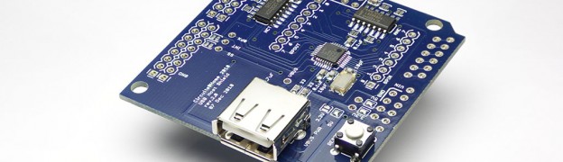
One of my favorite Arduino shield is the USB Host Shield by circuits @ home. Both the hardware and the software of this shield are excellent and well written.
I was playing around with the shield by connecting a USB Missile Launcher and had a closer look at the shield. I realized when I had a closer look that the GPIO pins of the Max 3421 IC, present in the shield have separate headers and are not directly used by the shield.
In this tutorial, I will explain how you can access these GPIO pins of the Max 3421 IC which present in the shield.
Max 3421 IC
The USB Host Shield uses the Max 3421 IC to provide the USB Host capabilities for Arduino.
If you are wondering what is an USB Host shield or what is USB Host mode, then do read my article about USB Host Shield and Arduino, which I wrote a couple of weeks ago.
GPIO Pins
Every micro controller will have a set of pins that can be used for general input and output. These pins are know as GPIO (General Purpose Input and Output) pins. In Arduino, the GPIO pins of the AVR micro-controller are mapped to the headers that are available on both sides of the board. The Max 3421 IC that is used inside the shield has 8 input and 8 output pins.
Accessing the GPIO pins
After realizing about the GPIO pins, I immediately was trying to see if there is a way by which I can access them. I checked out the datasheet and found that these pins are controlled by the IOPINS1 and IOPINS1 registers (similar to the ports in AVR/Arduino). I then checked the USB Host Shield library and found two methods, gpioRd() and gpioWr() that allows you to access these pins.
Arduino Library
The problem with those two functions is that, you have to read or write all 8 pins at once, and then do some bit manipulation to control individual pins. The bit manipulation that you have to do is not complex, but at the same time it is not as easy as doing digitalWrite() or digitalRead().
So I immediately wrote an Arduino library, that abstracts out this bit manipulation and provides simple functions like write() and read(), that can be used to write or read from the pins individually.
I have also created an example sketch which shows you how you can use this library to control the pins individually.
Video
You can see the library in action in the below video. Here I have connected 8 led’s to each of the GOut pins and I am controlling them separately.
Try out the library and do let me know if you have any feedback or comments.
Happy hacking 🙂